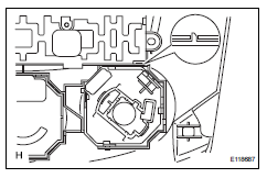
Toyota RAV4 (XA40) 2013-2018 Service Manual: Air conditioning control assembly (for manual air conditioning system)
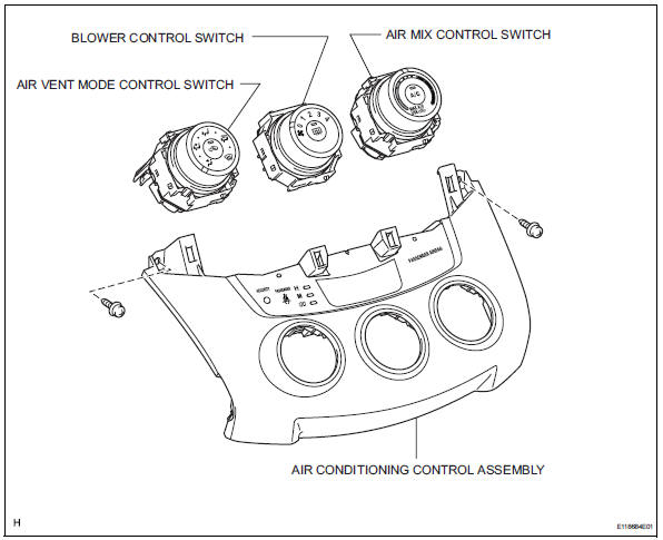
Components
Removal
- Disconnect cable from negative battery terminal
Notice:
Wait at least 90 seconds after disconnecting the cable from the negative (-) battery terminal to prevent airbag and seat belt pretensioner activation.
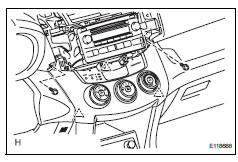
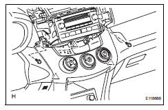
- Remove no. 2 Instrument cluster finish panel center (see page ip-5)
- Remove no. 1 Instrument cluster finish panel center (see page ip-5)
- Remove radio receiver assembly (see page ip-5)
- Remove air conditioning control assembly
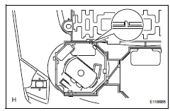
- Remove the 2 screws.
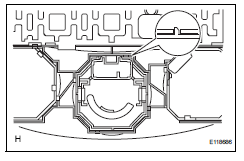
- Using a screwdriver, detach the 3 clips.
Hint:
Tape the screwdriver tip before use.
- Disconnect the connectors and remove the air conditioning control.
- Remove air mix control switch
- Detach the 2 claws and remove the air mix control switch.
- Remove blower control switch
- Detach the 2 claws and remove the blower control switch.
- Remove air vent mode control switch
- Detach the 2 claws and remove the mode control switch.
Installation
- Install air vent mode control switch
- Attach the 2 claws to install the mode control switch.
- Install blower control switch
- Attach the 2 claws to install the blower control switch.
- Install air mix control switch
- Attach the 2 claws to install the air mix control switch.
- Install air conditioning control assembly
- Connect the connectors.
- Attach the 3 clips to install the air conditioning control.
- Install the 2 screws.
- Install radio receiver assembly (w/ radio receiver) (see page ip-10)
- Install no. 1 Instrument cluster finish panel center (see page ip-10)
- Install no. 2 Instrument cluster finish panel center (see page ip-10)
- Connect cable to negative battery terminal
- Check srs warning light
- Check the srs warning light (see page rs-37).
 Air conditioning control assembly (for automatic air conditioning system)
Components
Removal
Disconnect cable from negative battery
terminal
Notice:
Wait at least 90 seconds after disconnecting the
cable from the negative (-) battery terminal to
prevent air ...
 Lighting
...
Other materials:
On-vehicle inspection
Inspect refrigerant pressure with
manifold gauge set
This method uses a manifold gauge set to locate
problem areas. Read the manifold gauge pressure
when these conditions are established. Test
conditions:
Temperature at the air inlet is 30 to 35°c (86 to
95°f).
Engine is ...
Torque converter and drive plate
Inspection
Inspect torque converter clutch assembly
Inspect the one-way clutch.
Install sst to the inner race of the one-way
clutch.
Sst 09350-32014 (09351-32010)
Set sst so that it fits in the notch of the
converter hub and in the outer race of the oneway
clutch.
...
Condenser
Components
On-vehicle inspection
Inspect cooler condenser assembly
If the fins of the cooler condenser are dirty, clean
them with water. Dry the fins with compressed air.
Notice:
Do not damage the fins of the condenser.
If a fin of the cooler condenser is bent, straighte ...
