Toyota RAV4 (XA40) 2013-2018 Service Manual: General information
A large number of ecu controlled systems are used in the rav4. In general, ecu controlled systems are considered to be very intricate, requiring a high level of technical knowledge to troubleshoot. However, most problem checking procedures only involve inspecting the ecu controlled system's circuits one by one. An adequate understanding of the system and a basic knowledge of electricity is enough to perform effective troubleshooting, accurate diagnoses and necessary repairs.
For using intelligent tester
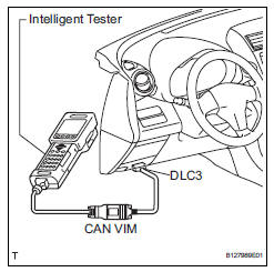
Connect the cable of the intelligent tester to the dlc3, turn the ignition switch on and attempt to use the tester. If the display indicates that a communication error has occurred, there is a problem either with the vehicle or with the tester.
* If communication is normal when the tester is connected to another vehicle, inspect the dlc3 of the original vehicle.
* If communication is still not possible when the tester is connected to another vehicle, the problem may be in the tester itself. Consult the service department listed in the tester's instruction manual.


Other materials:
Combination meter ecu communication stop mode
Description
Wiring diagram
Inspection procedure
Notice:
Turn the ignition switch off before measuring the resistances of the
main wire and the branch
wire.
After the ignition switch is turned off, check that the key reminder
warning system and light
reminder warning system ...
Disassembly (2005/11-2006/01)
Remove front axle inboard joint boot no. 2
Clamp lh
One touch type:
Using a screwdriver, remove the no. 2 Inboard
joint boot clamp, as shown in the illustration.
Claw engagement type:
Using needle-nose pliers, remove the no. 2
Inboard joint boot clamp, as shown in t ...
Engine (ignition) switch
(vehicles without a
smart key system)
Starting the engine
Check that the parking brake is set.
Check that the shift lever is set in p.
Firmly depress the brake pedal.
Turn the engine switch to the ŌĆ£startŌĆØ position to start the engine.
Changing the engine switch positions
ŌĆ£LockŌĆØ
The steering wheel is locked an ...
