Toyota RAV4 (XA40) 2013-2018 Service Manual: Installation
Hint:
- Use the same procedures for the rh side and lh side.
- The procedures listed below are for the lh side.
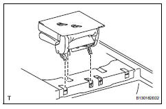
- Install no. 2 Seat leg box protector
- Attach the clip to install the protector.
- Install the clip.
- Install rear no. 1 Floor mat support side plate
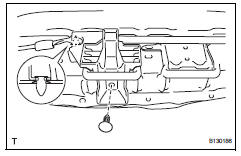
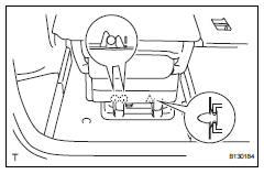
- Install rear no. 2 Seat assembly
- Fully tilt the seatback forward.
- Place the seat onto the lock striker.
- Fully lock the seat to the lock striker.
Hint:
- Lock the rear side, then lock the front side.
- Confirm that the seat is firmly locked to the lock striker.
- Install the rear no. 2 Seat link with the 2 nuts.
Torque: 18 n*m (184 kgf*cm, 13 ft.*Lbf)
- Install the seat to the rear no. 2 Seat link with the 2
bolts.
Torque: 18 n*m (184 kgf*cm, 13 ft.*Lbf)
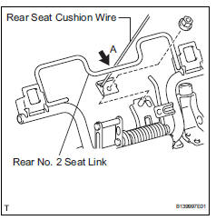
- Pass the rear seat cushion wire underneath the rear no. 2 Seat link part labeled a.
Notice:
If the wire is not installed as described, the seat will not move properly.
- Install the rear seat cushion wire to the rear no. 2
Seat link with the nut.
Torque: 18 n*m (184 kgf*cm, 13 ft.*Lbf)
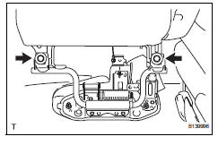
- Install no. 2 Seat leg cover lh
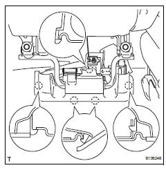
- Attach the 5 claws to install the leg cover.
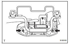
- Install no. 2 Seat hinge cover lh
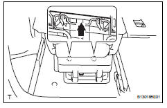
- Push the hinge cover in the direction indicated by the arrow in the illustration to attach the 2 claws.
- Attach the 2 claws and clip to install the hinge cover.
- Return the seatback to the upright position.
 Reassembly
Hint:
Use the same procedures for the rh side and lh side.
The procedures listed below are for the lh side.
Install seat lock release band
Install the band with nut.
Hint:
After ...
 Power seat switch
Inspection
Inspect front power seat switch
Measure the resistance between the terminals when
each switch is operated.
Standard resistance
Slide switch
Front vertical switch
Lif ...
Other materials:
Reassembly
Install sliding roof drive cable
Using a screwdriver, slide the sliding roof drive
cable sub-assemblies in the direction indicated by
the arrow in the illustration to install them.
Hint:
Tape the screwdriver tip before use.
Engage the 2 claws and install the sliding roof ...
Valve clearance
Adjustment
Disconnect cable from negative battery
terminal
Caution:
Wait at least 90 seconds after disconnecting the
cable from the negative (-) battery terminal to
prevent airbag and seat belt pretensioner activation.
Remove front wheel rh
Remove no. 1 Engine under cover
Remove ...
Pressure control solenoid "d" electrical (shift solenoid valve slt)
Description
Refer to dtc p2714 (see page ax-91).
Monitor description
When an open or short in the shift solenoid valve slt circuit is detected,
the ecm interprets this as a fault.
The ecm will illuminate the mil and store the dtc.
Monitor strategy
Typical enabling conditions
...
