Toyota RAV4 (XA40) 2013-2018 Service Manual: Parking brake cable
Components
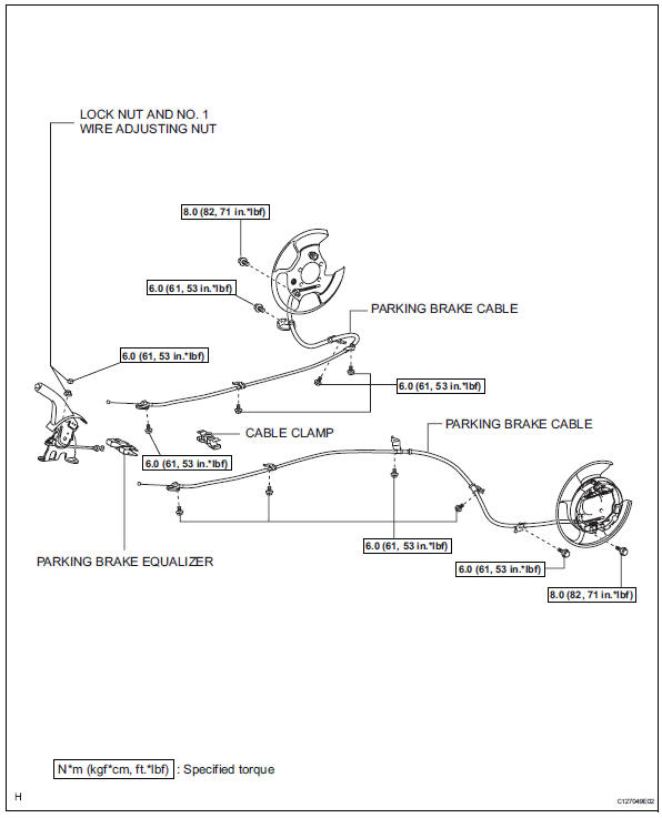
Removal
- Remove rear console box sub-assembly
- Remove the rear console box (see page ip-16).
Hint:
Refer to the procedures from the removal of the no.
1 Console upper panel garnish up until the removal of the rear console box sub-assembly.
- Loosen lock nut and no. 1 Wire adjusting nut (see page pb-1)
- Remove parking brake equalizer
- Disconnect the 3 cable ends and then remove the equalizer.
- Remove rear wheel
- Remove parking brake cable
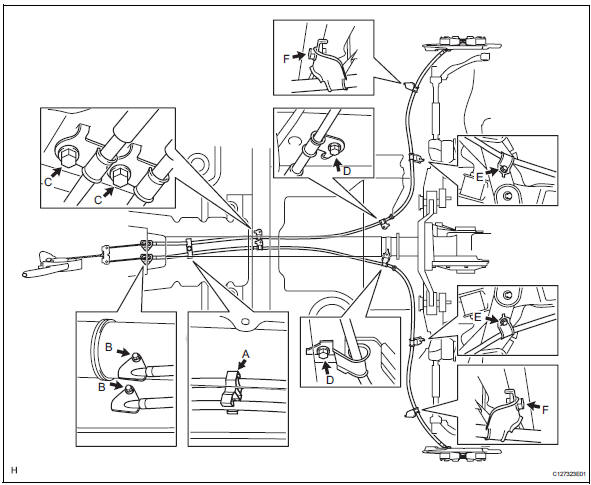
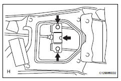
- Remove the cable clamp (labeled a) from the body.
- Remove the casing cap bolt (labeled b) from the body.
- Remove the clamp bolt (labeled c) from the body.
- Remove the clamp bolt (labeled d) from the crossmember.
- Remove the clamp bolt (labeled e) from the rear suspension crossmember.
- Remove the clamp bolt (labeled f) from the trailing arm.
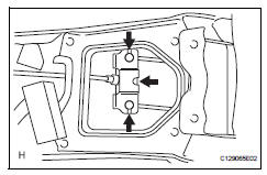
- Disconnect the cable from the parking brake shoe lever and backing plate.
- Disconnect the cable from the lever (see page pb-13).
- Remove the bolt and disconnect the cable from the backing plate.
Installation
- Install parking brake cable
- Connect the cable to the backing plate and parking brake shoe lever.
- Pass the cable through the backing plate, and then connect the cable to the lever.
- Install the cable to the backing plate with the bolt.
Torque: 8.0 N*m (82 kgf*cm, 71 in.*Lbf)
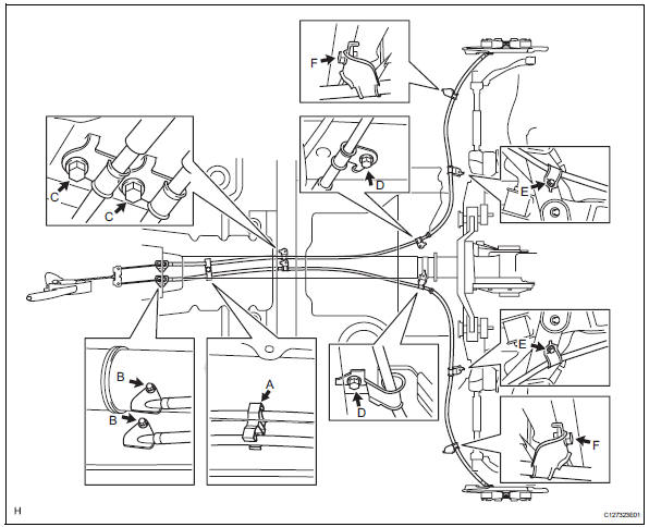
- Install the clamp and clamp bolt (labeled f) to the trailing arm.
Torque: 6.0 N*m (61 kgf*cm, 53 in.*Lbf)
Notice:
Securely install the clamp.
- Install the clamp and clamp bolt (labeled e) to the rear suspension crossmember.
Torque: 6.0 N*m (61 kgf*cm, 53 in.*Lbf)
Notice:
Securely install the clamp.
- Install the clamp and clamp bolt (labeled d) to the
crossmember.
Torque: 6.0 N*m (61 kgf*cm, 53 in.*Lbf)
Notice:
Securely install the clamp.
- Install the clamp and clamp bolt (labeled c) to the body.
Torque: 6.0 N*m (61 kgf*cm, 53 in.*Lbf)
Notice:
Securely install the clamp.
- Install the casing cap and casing cap bolt (labeled
b) to the body.
Torque: 6.0 N*m (61 kgf*cm, 53 in.*Lbf)
Notice:
Securely install the casing cap.
- Install the cable clamp (labeled a) to the body.
Notice:
Securely install the clamp.
- Install parking brake equalizer
- Connect the 3 cable ends to the equalizer.
- Install rear wheel
Torque: 103 n*m (1,050 kgf*cm, 76 ft.*Lbf)
- Adjust parking brake lever travel (see page pb-2)
- Install rear console box sub-assembly
- Install the rear console box (see page ip-23).
Hint:
Refer to the procedures from the installation of the rear console box sub-assembly up until the installation of the no. 1 Console upper panel garnish.
 Parking brake lever
Components
On-vehicle inspection
Check parking brake switch assembly
Remove the rear console box (see page ip-16).
Hint:
Refer to the procedures from the removal of the no.
...
 Parking brake assembly
Components
Disassembly
Hint:
Use the same procedures for the lh side and rh side.
The procedures listed below are for the lh side.
Remove rear wheel
Disconnect rear disc brake cyli ...
Other materials:
Installation
Install no. 2 Radiator grille lower
Install the radiator grille and attach the 16 claws.
Install no. 1 Radiator grille lower
Install the radiator grille and attach the 16 claws.
Install radiator grille
Install the radiator grille with the 6 claws.
...
Exhaust gas precautions
Harmful substance to the human body is included in exhaust
gases if inhale.
Caution
Exhaust gases include harmful carbon monoxide (co), which is colorless and
odorless. Observe the following precautions.
Failure to do so may cause exhaust gases enter the vehicle and may lead to
an accident c ...
Removal
Hint:
Use the same procedures for the rh side and lh side.
The procedures listed below are for the lh side.
When removing the moulding, heat the vehicle body and
moulding using a heat light.
Standard heating temperature
Notice:
Do not heat the vehicle body and moulding
excessively.
...
