Toyota RAV4 (XA40) 2013-2018 Service Manual: Rear power outlet socket
Components
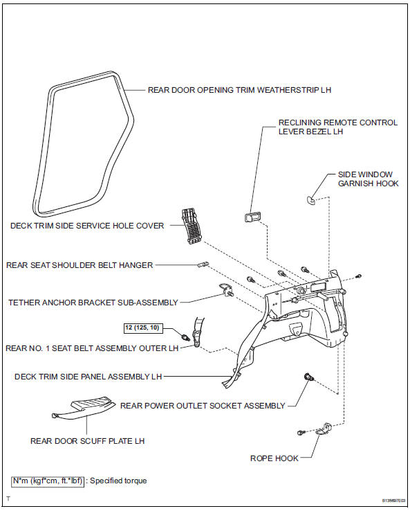
Removal
- Disconnect cable from negative battery terminal
Caution:
Wait at least 90 seconds after disconnecting the cable from the negative (-) battery terminal to prevent airbag and seat belt pretensioner activation.
- Remove rear door scuff plate lh (see page ir-26)
- Remove rear door opening trim weatherstrip lh
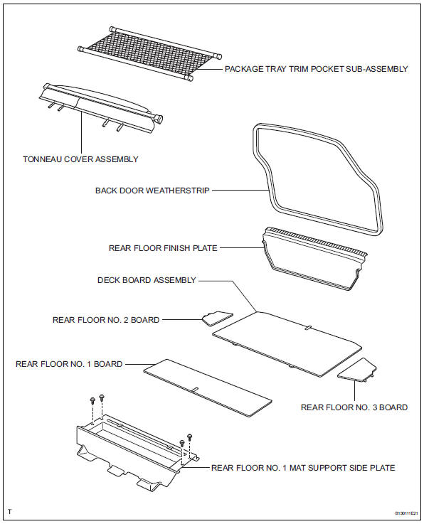
- Remove package tray trim pocket subassembly
- Remove tonneau cover assembly
- Remove rear floor no. 1 Board
- Remove deck board assembly
- Remove rear floor no. 3 Board
- Remove rear floor no. 2 Board
- Remove rear floor no. 1 Mat support side plate (see page ir-31)
- Remove back door weatherstrip
- Remove rear floor finish plate (see page ir- 31)
- Remove reclining remote control lever bezel lh
- Remove tether anchor bracket subassembly
- Remove deck trim side panel assembly lh (w/ rear no. 2 Seat) (see page ir-32)
- Remove deck trim side panel assembly lh (w/o rear no. 2 Seat) (see page ir-32)
- Remove rear power outlet socket assembly
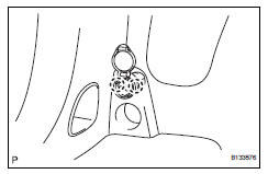
- Detach the 2 claws fittings and remove the socket.
Installation
- Install rear power outlet socket assembly
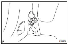
- Attach the 2 claw fittings to install the socket.
- Install deck trim side panel assembly lh (w/ o rear no. 2 Seat) (see page ir-52)
- Install deck trim side panel assembly lh (w/ rear no. 2 Seat) (see page ir-53)
- Install tether anchor bracket subassembly
- Install reclining remote control lever bezel lh
- Install rear floor finish plate (see page ir- 55)
- Install back door weatherstrip
- Install rear floor no. 1 Mat support side plate (see page ir-55)
- Install rear floor no. 2 Board
- Install rear floor no. 3 Board
- Install deck board assembly
- Install rear floor no. 1 Board
- Install tonneau cover assembly
- Install package tray trim pocket subassembly
- Install rear door opening trim weatherstrip lh
- Install rear door scuff plate lh (see page ir-59)
- Connect cable to negative battery terminal
 Center power outlet socket (for ac power supply)
Components
Removal
Disconnect cable from negative battery
terminal
Caution:
Wait at least 90 seconds after disconnecting the
cable from the negative (-) battery terminal to
prevent ai ...
 Maintenance
...
Other materials:
Tire pressure warning receiver (w/ antenna)
Components
...
Turn signal light circuit
Description
The turn signal flasher relay (marking: flsh) in the main body ecu turns on
when it receives signals
from the headlight dimmer switch integrated with the turn signal switch, causing
the turn signal lights to
flash.
Wiring diagram
Inspection procedure
Check operation of t ...
Installation (2006/01- )
Install abs and traction actuator assembly with bracket
Notice:
do not remove the hole plug before connecting the
brake tube. new actuators are filled with brake fluid.
Install the actuator with bracket with the 3 nuts.
Torque: 19 n*m (194 kgf*cm, 14 ft.*Lbf)
Hint:
The nuts should b ...
