Toyota RAV4 Service Manual: Air fuel ratio sensor
Components
On-vehicle inspection
- Check air fuel ratio compensation system
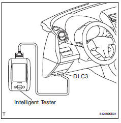
- Connect the intelligent tester to the dlc3.
- Turn the ignition switch on.
- Select the following menu items: data list / a/fs b1 s1 and o2s b1 s2.
- Warm up the a/f sensor with the engine speed at 2,500 rpm for approximately 2 minutes.
- Keep the engine speed at 2,500 rpm and confirm that the display of "a/fs b1 s1" is as shown in the illustration.
Hint:
- The illustration may slightly differ from the display on the intelligent tester.
- Only the intelligent tester displays the waveform of the a/f sensor.
- Confirm that the display of "o2s b1 s2" changes between 0 to 1 v with the engine speed at 2,500 rpm.
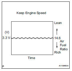
Ok: the voltage output oscillates more than 8 times in 10 seconds.
Notice:
- Perform the check immediately after warming the engine up.
- If the voltage variation could not be verified, warm up the a/f sensor again. If it could not be verified even after warming up the sensor again, check for dtcs (see page es-292).
Removal
- Disconnect cable from negative battery terminal
Caution:
Wait at least 90 seconds after disconnecting the cable from the negative (-) battery terminal to prevent airbag and seat belt pretensioner activation.
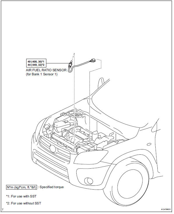
- Remove air fuel ratio sensor (for bank 1 sensor 1)
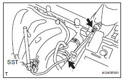
- Disconnect the sensor connector.
- Using sst, remove the sensor from the exhaust manifold.
Sst 09224-00010
Inspection
- Inspect air fuel ratio sensor (for bank 1 sensor 1)
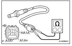
- Measure the resistance of the sensor.
Standard resistance 
If the resistance is not as specified, replace the sensor.
Installation
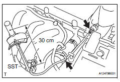
- Install air fuel ratio sensor (for bank 1 sensor 1)
- Using sst, install the sensor to the exhaust manifold.
Sst 09224-00010
Torque: 40 n*m (408 kgf*cm, 30 ft.*Lbf) for use with sst
44 N*m (449 kgf*cm, 32 ft.*Lbf) for use without sst
Hint:
- Use a torque wrench with a fulcrum length of 30 cm (11.81 In.).
- Make sure sst and wrench are connected in a straight line.
- Connect the sensor connector.
- Connect cable to negative battery terminal
- Check for exhaust gas leaks
 Ventilation valve
Components
Removal
Remove no. 1 Engine cover (see page em-22)
Remove ventilation valve sub-assembly
Disconnect the ventilation hose from the ventilation
valve.
Using a ...
 Heated oxygen sensor
Components
Removal
Disconnect cable from negative battery
terminal
Caution:
Wait at least 90 seconds after disconnecting the
cable from the negative (-) battery terminal to
prevent ai ...
Other materials:
Diagnosis system
Description
Key reminder warning system data can be read
through the data link connector 3 (dlc3) of the
vehicle. When the system seems to be
malfunctioning, use the intelligent tester (with can
vim) to check for malfunctions and perform repairs.
Check dlc3
The vehi ...
Front wiper rubber
Components
Removal
Remove front wiper blade
Detach the claw as shown in the illustration.
Remove the wiper blade as shown in the illustration.
Notice:
Do not fold the wiper arm with the wiper blade
removed. The arm tip may damage the
windshield surface.
Rem ...
Torque converter clutch solenoid performance (shift solenoid valve dsl)
Description
The ecm uses the signals from the throttle position sensor, air-flow meter,
turbine (input) speed sensor,
intermediate (counter) shaft speed sensor and crankshaft position sensor to
monitor the engagement
condition of the lock-up clutch.
Then the ecm compares the engagement ...
