Toyota RAV4 Service Manual: Back-up light circuit
Description
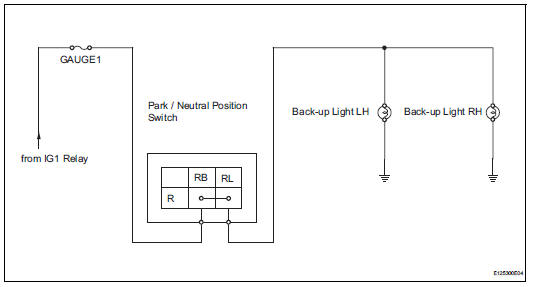
The park / neutral position switch turns on when the shift lever is moved into the r position, causing the back-up lights to illuminate.
Wiring diagram
Inspection procedure
- Inspect fuse (gauge1)
- Remove the gauge1 fuse from the instrument panel junction block.
- Measure the resistance of the fuse.
Standard resistance:
below 1

- Inspect back-up light
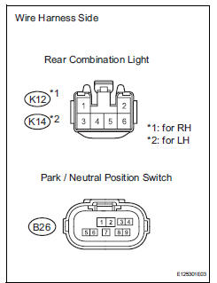
- Remove the rear combination light.
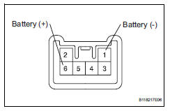
- Connect the positive (+) lead from the battery to terminal 6 and the negative (-) lead to terminal 1, then check that the light comes on.
Ok: light comes on.

- Inspect park / neutral position switch
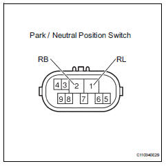
- Disconnect the b26 park / neutral position switch connector.
- Measure the resistance of the switch.
Standard resistance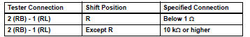

- check wire harness (park / neutral position switch - battery)
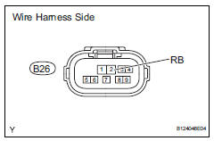
- Disconnect the b26 park / neutral position switch connector.
- Measure the voltage of the wire harness side connector.
Standard voltage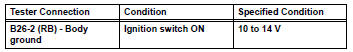

- Check wire harness (park / neutral position switch - back-up light)
- Disconnect the b26 park / neutral position switch connector.
- Disconnect the k12 and k14 rear combination light assembly connectors
- Measure the resistance of the wire harness side connectors.
Standard resistance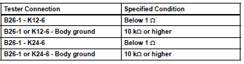

Repair or replace harness and connector (back-up light - body ground)
 Hazard warning switch circuit
Description
When the hazard warning signal switch is turned on, the turn signal flasher
relay (marking: flsh) in the
main body ecu turns on to flash the hazard warning signal lights.
Wiring diagr ...
 Light control switch circuit
Description
This circuit detects the state of the headlight dimmer switch.
Wiring diagram
Inspection procedure
Read value of intelligent tester (main body ecu)
Connect the intelligent ...
Other materials:
Power steering ecu
Components
Removal
Disconnect cable from negative battery
terminal
Remove instrument panel sub-assembly
upper
Remove the instrument panel (see page ip-4).
Remove power steering ecu
Disconnect the 4 connectors.
Remove the 3 nuts and remove the power steering
e ...
Footwell light circuit
Description
The main body ecu receives information regarding the door lock position
switch and ignition switch, and
turns on each foot light.
Wiring diagram
Inspection procedure
Perform active test by intelligent tester (main body ecu)
Connect the intelligent tester (with can vim ...
Center power outlet socket
Components
Removal
Disconnect cable from negative battery
terminal
Caution:
Wait at least 90 seconds after disconnecting the
cable from the negative (-) battery terminal to
prevent airbag and seat belt pretensioner activation.
Remove no. 1 Console upper panel garnish
(see page ...
