Toyota RAV4 (XA40) 2013-2018 Service Manual: Back-up power source circuit
Description
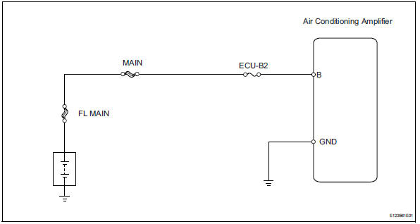
This is the back-up power source circuit for the air conditioning amplifier. Power is supplied even when the ignition switch is turned off and is used for functions such as the diagnostic trouble code memory.
wiring diagram
Inspection procedure
- Inspect fuse (ecu-b2)
- Remove the ecu-b2 fuse from the engine room no. 2 Relay block.
- Measure the resistance of the fuse.
Standard resistance:
below 1 

- Check wire harness (air conditioning amplifier - battery)
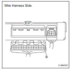
- Disconnect the e37 amplifier connector.
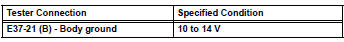
- Measure the voltage of the wire harness side connector.
Standard voltage

- Check wire harness (air conditioning amplifier - body ground)
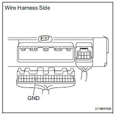
- Disconnect the e37 amplifier connector.
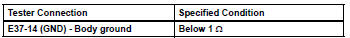
- Measure the resistance of the wire harness side connector.
Standard resistance

Proceed to next circuit inspection shown in problem symptoms table
 Ig power source circuit
Description
This is the main power source supplied to the air conditioning amplifier when
the ignition switch is on
(ig). This power source is used for operating components, such as the air
cond ...

Other materials:
Ig power supply voltage malfunction
Description
The power steering ecu distinguishes the ignition switch status as on or off
through the ig power
source circuit.
Wiring diagram
Inspection procedure
Read value of intelligent tester (ig power supply)
Connect the intelligent tester (with can vim) to the
dlc3.
...
Inspection
Inspect front seat outer belt assembly
Notice:
Do not disassemble the retractor.
Before installing the outer belt, check the elr.
When the inclination of the retractor is 15Đ or
less, check that the belt can be pulled from the
retractor. When the inclination of the retractor ...
Inner rear view mirror
Components
Removal
Remove inner rear view mirror assembly
Disengage the 2 claws and separate the inner rear
view mirror cover as shown in the illustration.
Remove the inner rear view mirror as shown in the
illustration.
Installation
Install inner rear view mir ...
