Toyota RAV4 Service Manual: Blower motor circuit
Description
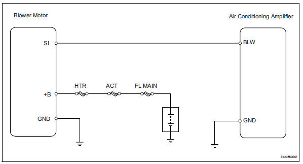
The blower motor is operated by signals from the air conditioning amplifier. Blower motor speed signals are transmitted in accordance with changes in the duty ratio.

Wiring diagram
Inspection procedure
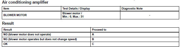
- Perform active test by intelligent tester (blower motor)
- Connect the intelligent tester to (with can vim) the dlc3.
- Turn the ignition switch on and turn the intelligent tester main switch on.
- Select the item below in the active test, and then check that the blower motor operates.

- Inspect fuse (htr)
- Remove the htr h-fuse from the engine room no. 2 Relay block.
- Measure the resistance of the h-fuse.
Standard resistance:
below 1 

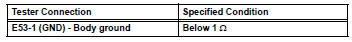
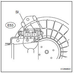
- Check wire harness (blower motor - body ground)
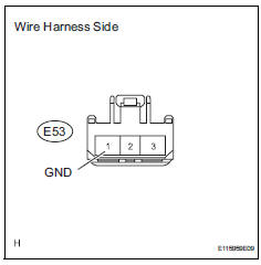
- Disconnect the e53 motor connector.
- Measure the resistance of the wire harness side connector.
Standard resistance

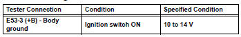
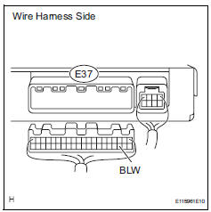
- Check wire harness (blower motor - battery)
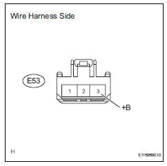
- Disconnect the e53 motor connector.
- Measure the voltage of the wire harness side connector.
Standard voltage

- Check blower w/ fan motor sub-assembly
- Disconnect the e37 amplifier connector.
- Connect the e53 motor connector.
- Measure the voltage of the connector.
Standard voltage


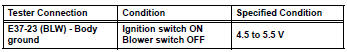
- Check wire harness (air conditioning amplifier - body ground)
- Disconnect the e37 amplifier connector.
- Measure the voltage of the wire harness side connector
Standard voltage

- Check air conditioning amplifier
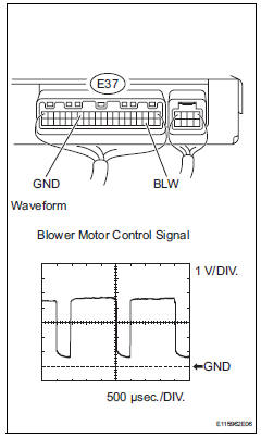
- Remove the air conditioning amplifier with its connectors still connected.
- Check the waveform of the amplifier connector.
Ok: waveform is as shown in the illustration.
Hint:
The waveform varies with the blower level.


Replace blower w/ fan motor sub-assembly
 Air conditioning control panel does not operate
Description
This circuit consists of the air conditioning control and the air
conditioning amplifier. When the air
conditioning control is operated, signals are transmitted to the air
conditioni ...
 Compressor circuit
Description
When the a/c switch is turned on, the magnetic clutch on signal is sent from
the air conditioning
amplifier. Then the mg clt relay turns on to operate the magnetic clutch.
Wiring diag ...
Other materials:
Front brake
Components
Removal
Hint:
Use the same procedures for the lh side and rh side.
The procedures listed below are for the lh side.
Remove front wheel
Drain brake fluid
Notice:
Wash off brake fluid immediately if it comes in
contact with any painted surface.
Disconnec ...
Steering angle sensor circuit malfunction
Description
The steering sensor signal is sent to the skid control ecu via the can
communication system. When
there is a malfunction in the can communication system, it is detected by the
steering sensor zero point
malfunction diagnostic function.
Wiring diagram
Inspection proce ...
Camshaft position "a" actuator circuit (bank 1)
Dtc P0010 Camshaft
position "a" actuator circuit (bank
1)
Description
The variable valve timing (vvt) system includes the ecm, ocv and vvt
controller. The ecm sends a
target duty-cycle control signal to the ocv. This control signal regulates the
oil pressure supplied to the ...
