Toyota RAV4 (XA40) 2013-2018 Service Manual: Brake pedal load sensing switch
Description
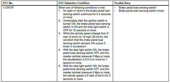
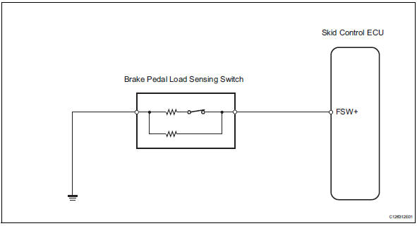
The brake pedal load sensing switch is turned on when the brake pedal is depressed with force exceeding a predetermined level.
The skid control ecu detects if the brake pedal is depressed or not via this circuit.
Wiring diagram
Inspection procedure
Notice:
When replacing the brake actuator assembly, perform zero point calibration (see page bc-24).
Hint:
If dtc c1249/49 is output, repair it before repairing dtc c1267/67 based on the flowchart below.
- Read value of intelligent tester (brake pedal load sensing switch)
- Check the data list for proper functioning of the brake pedal load sensing switch.
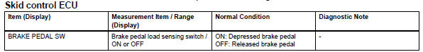
Ok: on (brake pedal is depressed) appears on the screen.


- Inspect brake pedal load sensing switch
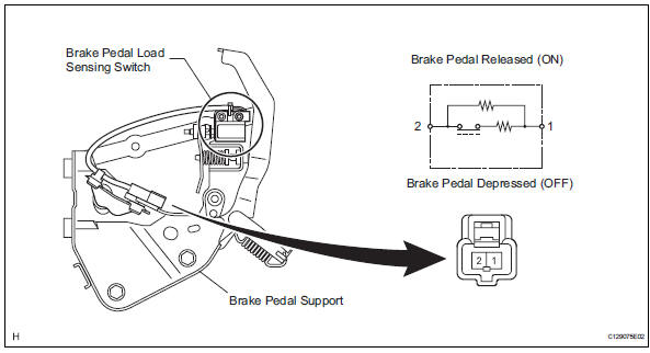
Notice:
- Do not remove the brake pedal load sensing switch from the brake pedal.
- When there is a malfunction in the brake pedal load sensing switch, replace the brake pedal.
- Turn the ignition switch off.
- Disconnect the brake pedal load sensing switch connector.
- Measure the resistance of the switch.
Standard resistance


- Check wire harness (skid control ecu - brake pedal load sensing switch)
- Disconnect the a19 ecu connector.
- Measure the resistance of the wire harness side connectors.
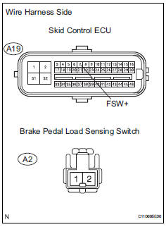
Standard resistance 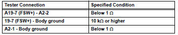

- Reconfirm dtc
- Clear the dtc (see page bc-47).
- Check if the same dtc is recorded (see page bc-47).
Result 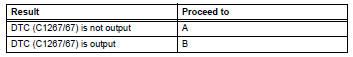

Use simulation method to check
 Open in pump motor circuit
Description
The motor relay drives the pump motor based on a signal from the skid control
ecu.
Wiring diagram
Refer to dtc c0273/13, c0274/14, c1361/91 (see page bc-79).
Inspection proce ...
 Steering angle sensor zero point malfunction
Description
The skid control ecu learns the steering sensor zero point every time the
ignition switch is turned on and
the vehicle is driven at 35 km/h (22 mph) or more for approximately 5 sec ...
Other materials:
Input speed sensor circuit no signal
Description
This sensor detects the rotation speed of the turbine, which shows the input
revolution of the transaxle. By
comparing the input speed signal (nt) with the counter gear speed sensor signal
(nc), the ecm detects
the shift timing of the gears and controls the engine torque and ...
Terminals of ecu
Check power steering ecu
Hint:
Measurements cannot be performed on the c connector
side of the power steering ecu.
Measure the voltage and resistance of the
connectors.
If the result is not as specified, the ecu may have a
malfunction. ...
Front drive shaft assembly (for 2wd)
Components (2005/11-2006/01)
Components (2006/01- )
...
