Toyota RAV4 (XA40) 2013-2018 Service Manual: Center airbag sensor communication stop mode
Description
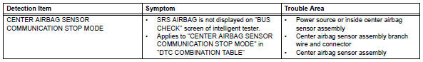
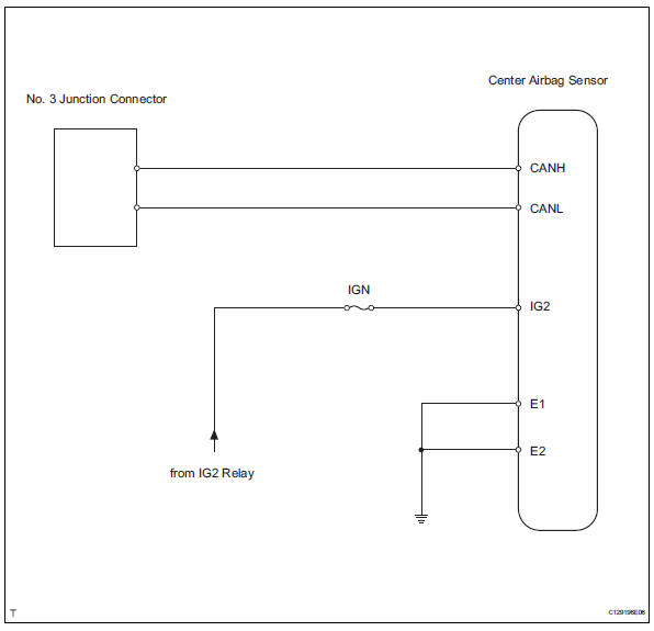
Wiring diagram
Inspection procedure
Notice:
- Turn the ignition switch off before measuring the resistances of the main wire and the branch wire.
- After the ignition switch is turned off, check that the key reminder warning system and light reminder warning system are not in operation.
- Before measuring the resistance, leave the vehicle for at least 1 minute and do not operate the ignition switch, any switches or doors. If doors need to be opened in order to check connectors, open the doors and leave them open.
Hint:
Operating the ignition switch, any switches or any doors triggers related ecu and sensor communication with the can, which causes resistance variation.
- Check can bus line for disconnection (center airbag sensor assembly branch wire)
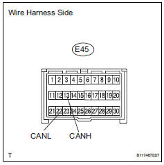
- Disconnect the e45 center airbag sensor connector.
- measure the resistance of the wire harness side connector.
Standard resistance 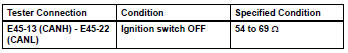

- Check wire harness (center airbag sensor assembly - battery and body ground)
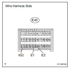
- Disconnect the e45 center airbag sensor connector.
- Measure the resistance of the wire harness side connector.
Standard resistance 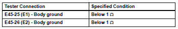
- Measure the voltage of the wire harness side connector.
Standard resistance 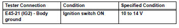

Replace center airbag sensor assembly
 Combination meter ecu communication stop mode
Description
Wiring diagram
Inspection procedure
Notice:
Turn the ignition switch off before measuring the resistances of the
main wire and the branch
wire.
After the ignition swi ...
 4Wd control ecu communication stop mode
Description
Hint:
For vehicle with 4wd only.
Wiring diagram
Inspection procedure
Notice:
Turn the ignition switch off before measuring the resistances of the
main wire and the bra ...
Other materials:
Rear drive shaft assembly
Components
Removal
Hint:
Use the same procedures for the rh side and lh side.
The procedures listed below are for the lh side.
Disconnect cable from negative battery
terminal
Caution:
Wait at least 90 seconds after disconnecting the
cable from the negative (-) battery termin ...
Terminals of ecu
Check instrument panel junction block (main body ecu)
Measure the voltage of the connectors.
If the result is not as specified, the junction block
(main body ecu) may have a malfunction. ...
Releasing and stowing the seat belt (for the rear center seat)
To release the hooked buckle
“b”, push the buckle release
button.
Release button
To release the hooked plate
A insert the mechanical key
Or plate B or the
wireless key into the hole on
the buckle.
When releasing the seat belt,
retract it slowly.
Stow th ...
