
Toyota RAV4 (XA40) 2013-2018 Service Manual: Communication

Description
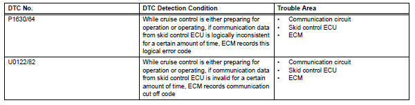
The skid control ecu sends signals such as cruise control cancel demand signals and brake operation demand from ecm response signals to the ecm when the cruise control system is in operation.
Inspection procedure
Hint:
This circuit uses can communication. Therefore, if there are any malfunctions in the communication circuit, one or more dtcs in the can communication system are output.
- Check can communication system
Refer to how to proceed with troubleshooting (see page ca-8).

Description
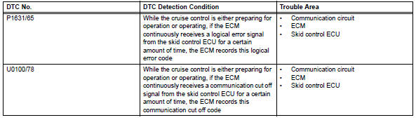
Therefore, if the skid control ecu detects a communication error from the ecm, it sends a malfunction signal back to the ecm.
Inspection procedure
Hint:
This circuit uses can communication. Therefore, if there are any malfunctions in the communication circuit, one or more dtcs in the can communication system are output.
- Check can communication system
Refer to how to proceed with troubleshooting (see page ca-8).
 Brake system malfunction
Description
This dtc is output when the vsc system has a problem. Check the vsc system
when this dtc is
output.
Inspection procedure
Hint:
This circuit uses can communication. Therefore ...
 Cruise control switch circuit
Description
This circuit sends signals to the ecm depending on the cruise control switch
condition. The battery
supplies positive (+) battery voltage to the cruise control switch. Then
terminal ...
Other materials:
Front seats
The seats can be adjusted
(longitudinally, vertically,
etc.). Adjust the seat to
ensure the correct driving
posture.
Adjustment procedure
Manual seat
Seat position adjustment
lever
Seatback angle adjustment
lever
Vertical height adjustment
lever (driver's side only)
Power seat
Seat posit ...
Test mode procedure
Hint:
By switching the skid control ecu from normal mode to
test mode, abnormality detection sensitivity is enhanced
and troubleshooting can be conducted efficiently.
Perform a sensor check in test mode after the speed
sensor or sensor rotor has been repaired or replaced.
If the igniti ...
Short in driver side squib 2nd step circuit
Description
The driver side squib 2nd step circuit consists of the center airbag sensor,
the spiral cable and the
steering pad.
The circuit instructs the srs to deploy when the deployment conditions are met.
These dtcs are recorded when a malfunction is detected in the driver side squi ...
