Toyota RAV4 (XA40) 2013-2018 Service Manual: Components (2005/11-2006/01)
Sliding roof ecu power source circuit
Description
If the sliding function and tilt function do not operate, there may be a malfunction in the sliding roof ecu power source circuit.
Wiring diagram

Inspection procedure
- Perform active test by intelligent tester (sliding roof operation)
- Select the active test, use the intelligent tester to generate a control command, and then check that the sliding roof operates normally.
Sliding roof ecu
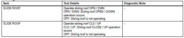
Ok: sliding roof operates normally.

- Inspect fuse (s/roof, ecu-ig1)
- Remove the s/roof and ecu-ig1 fuses from the instrument panel junction block.
- Measure the resistance of the fuses.
Standard resistance:
below 1 

- Check wire harness (sliding roof drive gear - body ground)
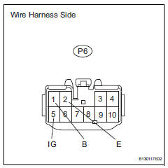
- Disconnect the p6 drive gear connector.
- Measure the voltage and resistance of the wire harness side connector.
Standard voltage 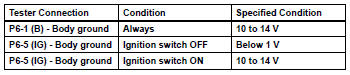
Standard resistance 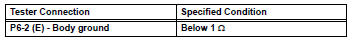

Replace sliding roof drive gear sub-assembly


Other materials:
Adjusting the settings manually
To adjust the fan speed, press
on
to increase the fan
speed and to
decrease the fan speed.
Press to turn the fan off.
To adjust the temperature setting, turn
clockwise to
increases the temperature and turn
counterclockwise to
...
Disassembly
Remove radio setting condenser
Remove the bolt and condenser.
Remove oil pressure switch
Using a 24 mm deep socket wrench, remove the sensor.
Remove engine coolant temperature sensor
Using sst, remove the sensor and gasket.
Sst 09817-33190
Remove c ...
Throttle / pedal position sensor / switch "d" circuit range / performance
Description
Hint:
Refer to dtc p2120 (see page es-282).
Monitor description
When the difference between the output voltages of vpa and vpa2 deviates from
the standard, the ecm
determines that the accelerator pedal position (app) sensor is malfunctioning.
The ecm turns on the mil
and th ...
