Toyota RAV4 (XA40) 2013-2018 Service Manual: Compressor circuit
Description
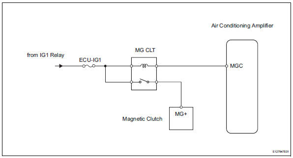
When the a/c switch is turned on, the magnetic clutch on signal is sent from the air conditioning amplifier. Then the mg clt relay turns on to operate the magnetic clutch.
Wiring diagram
Inspection procedure
- Perform active test by intelligent tester (a/c mag clutch)
- Connect the intelligent tester (with can vim) to the dlc3.
- Turn the ignition switch on and turn the intelligent tester main switch on.
- Select the item below in the active test and then check that the compressor magnetic relay operates.


- Inspect fuse (ecu-ig1)
- Remove the ecu-ig1 fuse from the instrument panel junction block.
- Measure the resistance of the fuse.
Standard resistance:
below 1 


- Inspect magnetic clutch relay (marking: mg clt)
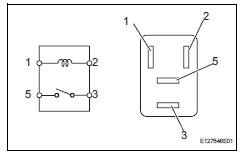
- Remove the magnetic clutch relay from the engine room no. 1 Relay block.
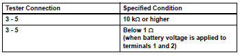
- Measure the resistance of the relay.
Standard resistance

- Check wire harness (air conditioning amplifier - battery)
- Disconnect the e37 amplifier connector.
- Measure the voltage of the wire harness side connector.
Standard voltage

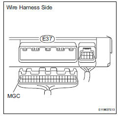
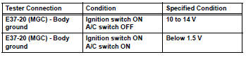
- Check air conditioning amplifier (mgc voltage)
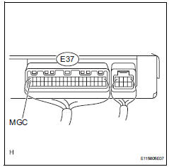
- Remove the air conditioning amplifier with its connectors still connected.
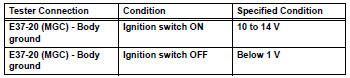
- Measure the voltage of the connector.
Standard voltage


- Check magnetic clutch
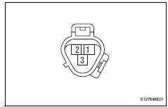
- Disconnect the b47 magnetic clutch connector.
- Connect the battery's positive (+) lead to terminal 3 of the magnetic clutch and the negative (-) lead to the body ground.
Ok: magnetic clutch is engaged.

Repair or replace wire harness (magnetic clutch - ecu-ig1)
 Blower motor circuit
Description
The blower motor is operated by signals from the air conditioning amplifier.
Blower motor speed signals
are transmitted in accordance with changes in the duty ratio.
Wiring diagra ...
 Ig power source circuit
Description
This is the main power source supplied to the air conditioning amplifier when
the ignition switch is on
(ig). This power source is used for operating components, such as the air
cond ...
Other materials:
Vehicle load limits
Vehicle load limits include total load capacity, seating capacity,
twr (trailer weight rating) and cargo capacity.
Total load capacity (vehicle capacity weight)
Total load capacity means the combined weight of occupants, cargo
and luggage.
Seating capacity: 5 occupants (front 2, rear 3)
Seatin ...
Inspection
Inspect front seat outer belt assembly
Notice:
Do not disassemble the retractor.
Before installing the outer belt, check the elr.
When the inclination of the retractor is 15Đ or
less, check that the belt can be pulled from the
retractor. When the inclination of the retractor ...
Driver side - side airbag sensor circuit malfunction
Description
The side airbag sensor lh consists of part including the diagnostic circuit
and the lateral deceleration
sensor.
When the center airbag sensor receives signals from the lateral deceleration
sensor, it determines
whether or not the srs should be activated.
Dtc b1620/21 is ...
