Toyota RAV4 (XA40) 2013-2018 Service Manual: Compressor lock sensor circuit
![]()
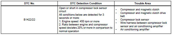
Description
This sensor sends 1 pulse per engine revolution to the air conditioning amplifier. If the ratio of the compressor speed divided by the engine speed is smaller than a predetermined value, the air conditioning amplifier turns the compressor off, and the indicator blinks at approximately 1 second intervals.
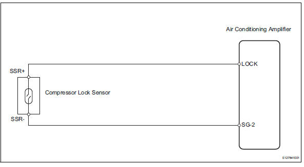
Wiring diagram
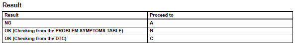
Inspection procedure
- Check air conditioning amplifier (lock signal)
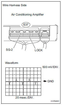
- Remove the air conditioning amplifier with its connectors still connected.
- Check the waveform of the amplifier connector.
Ok:
waveform is as shown in the illustration.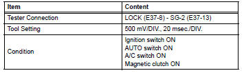

- Inspect compressor lock sensor
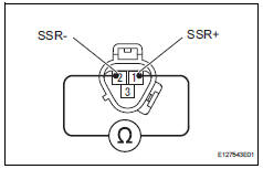
- Disconnect the b47 compressor lock sensor connector.
- Measure the resistance of the sensor.
Standard resistance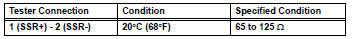

- Check wire harness (compressor lock sensor - air conditioning amplifier)
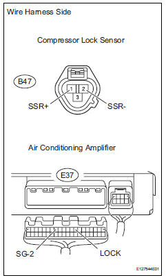
- Disconnect the b47 compressor lock sensor connector.
- Disconnect the e37 amplifier connector.
- Measure the resistance of the wire harness side connectors.
Standard resistance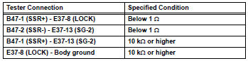

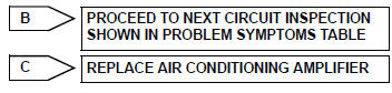
Replace air conditioning amplifier
 Solar sensor circuit (passenger side)
Description
The solar sensor, which is installed on the upper side of the instrument
panel, detects sunlight and
controls the air conditioning auto mode. The output voltage from the solar
se ...
 Pressure sensor circuit
Description
This dtc is output when the refrigerant pressure is either extremely low
(0.19 Mpa [2.0 Kgf/cm2, 28 psi]
or less) or extremely high (3.14 Mpa [32.0 Kgf/cm2, 455 psi] or more). The ...
Other materials:
Inspection
Inspect front seat outer belt assembly
Notice:
Do not disassemble the retractor.
Before installing the outer belt, check the elr.
When the inclination of the retractor is 15Đ or
less, check that the belt can be pulled from the
retractor. When the inclination of the retractor ...
Compressor and pulley (for 2az-fe)
Components
Removal
Discharge refrigerant from
refrigeration system (see page ac-172)
Disconnect cable from negative battery
terminal
Caution:
Wait at least 90 seconds after disconnecting the
cable from the negative (-) battery terminal to
prevent airbag and seat belt pretensione ...
Removal (2006/01- )
Disconnect cable from negative battery
terminal
Caution:
Wait at least 90 seconds after disconnecting the
cable from the negative (-) battery terminal to
prevent airbag and seat belt pretensioner activation.
Remove roof headlining assembly
Remove the roof headlining (see page ir ...
