Toyota RAV4 Service Manual: Diagnosis system
- Description
- Engine immobiliser system data and diagnostic trouble codes (dtcs) can be read through the vehicle's data link connector 3 (dlc3). In some cases, a malfunction may be occurring in the engine immobiliser system even though the security indicator light is not illuminated. When the system seems to be malfunctioning, use the intelligent tester to check for malfunctions and perform repairs.
- Check dlc3
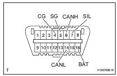
The vehicle's ecu uses the iso 15765-4 communication protocol. The terminal arrangement of the dlc3 complies with sae j1962 and matches the iso 15765-4 format.
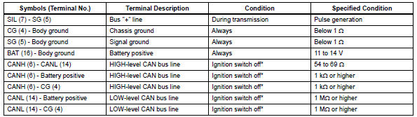
Notice:
*: Before measuring the resistance, leave the vehicle as is for at least 1 minute and do not operate the ignition switch, other switches or doors.
If the result is not as specified, the dlc3 may have a malfunction. Repair or replace the harness and connector.
Hint:
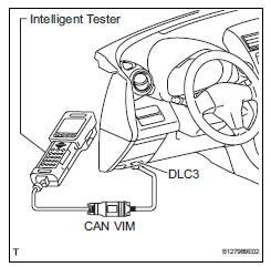
Connect the cable of the intelligent tester (with can vim) to the dlc3, turn the ignition switch on and attempt to use the intelligent tester. If the screen displays unable to connect to vehicle, a problem exists in the vehicle side or the tester side.
If the communication is normal when the tester is connected to another vehicle, inspect the dlc3 on the original vehicle.
If the communication is still not possible when the tester is connected to another vehicle, the problem is probably in the tester itself. Consult the service department listed in the tester's instruction manual.
 Terminals of ecu
Check transponder key amplifier
Disconnect the e5 amplifier connector.
Measure the resistance of the wire harness side
connector.
If the result is not as specified, there may b ...
 Dtc check / clear
Check dtc
Connect the intelligent tester (with can vim) to the
dlc3.
Turn the ignition switch on and turn the intelligent
tester on.
Select the following menu items: diagnosis /
...
Other materials:
Customize parameters
Hint:
The following items can be customized.
Notice:
When the customer requests a change in a function,
first make sure that the function can be customized.
Be sure to make a note of the current settings before
customizing.
When troubleshooting a function, first make sure that
the fu ...
Front fog light circuit
Description
The main body ecu controls the front fog light relay (marking: fr fog) when a
signal is received from
the headlight dimmer switch.
Wiring diagram
Inspection procedure
Perform active test by intelligent tester
Connect the intelligent tester (with can vim) to the
dlc3 ...
Lost communication with front passenger side - side airbag sensor assembly
Description
The side airbag sensor rh consists of parts including the diagnostic circuit
and the lateral deceleration
sensor.
When the center airbag sensor receives signals from the lateral deceleration
sensor, it determines
whether or not the srs should be activated.
Dtc b1627/82 i ...
