Toyota RAV4 (XA40) 2013-2018 Service Manual: Disassembly
- Remove radiator grille sub-assembly
- Remove the 4 bolts and 4 nuts.
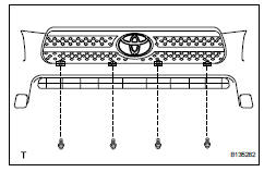
- Detach the 6 claws and remove the radiator grille.
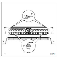
- Remove no. 1 Radiator grille lower
- Detach the 18 claws and remove the radiator grille.
- Remove no. 2 Radiator grille lower
- Detach the 16 claws and remove the radiator grille.
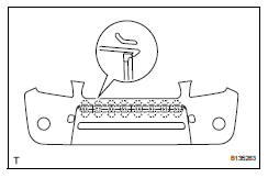
- Remove front bumper arm hole cover lh
- Detach the 2 claws and disconnect the arm hole cover.
- Remove the hook and bumper arm hole cover.
- Remove front bumper arm hole cover rh
- Use the same procedures described for the lh side.
- Remove fog light assembly lh
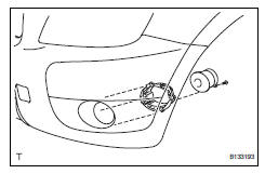
- Remove the screw and fog light.
- Remove the 3 bolts and fog light mounting bracket.
- Remove fog light assembly rh
Hint:
Use the same procedures described for the lh side.
- Remove front bumper hole cover lh (w/o fog light)
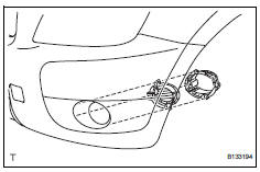
- Remove the 3 bolts, bumper hole cover and fog light mounting bracket.
- Remove front bumper hole cover rh (w/o fog light)
Hint:
Use the same procedures described for the lh side.
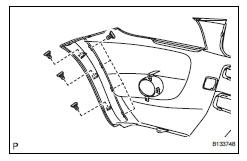
- Remove front bumper extension lh (for wide body)
- Detach the 7 outside moulding retainers and remove the extension lh.
Notice:
- If reusing the extension, take care not to damage the extension.
- Be careful not to damage the vehicle body.
- Remove front bumper extension rh (for wide body)
Hint:
Use the same procedures described for the lh side.
 Removal
Disconnect cable from negative battery
terminal
Caution:
Wait at least 90 seconds after disconnecting the
cable from the negative (-) battery terminal to
prevent airbag and seat belt preten ...
 Reassembly
V
Attach the 7 outside moulding retainers to install the
extension.
Install front bumper extension rh (for wide
body)
Hint:
Use the same procedures described for the lh side ...
Other materials:
Throttle / pedal position sensor / switch "A"
Hint:
These dtcs relate to the throttle position (tp) sensor.
Description
The tp sensor is mounted on the throttle body, and detects the opening angle
of the throttle valve. This
sensor is a non-contact type. It uses hall-effect elements in order to yield
accurate signals even in
extrem ...
Precaution
Handling precaution
When handling the electronic parts:
Avoid any impact to electronic parts such as
ecus and relays. Replace with new ones if
dropped or subjected to a severe blow.
Do not expose any electronic parts to high
temperatures and humidity.
Do not touch the connec ...
Ventilation valve
Components
Removal
Remove no. 1 Engine cover (see page em-22)
Remove ventilation valve sub-assembly
Disconnect the ventilation hose from the ventilation
valve.
Using a 22 mm deep socket wrench, remove the
ventilation valve.
Inspection
Inspect ventilation val ...
