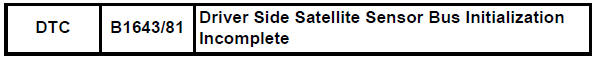
Toyota RAV4 Service Manual: Driver side satellite sensor bus initialization incomplete
Description
The side airbag sensor lh consists of part including the diagnostic circuit and the lateral deceleration sensor.
When the center airbag sensor receives signals from the lateral deceleration sensor, it determines whether or not the srs should be activated.
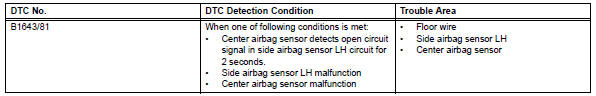
Dtc b1643/81 is set when a malfunction is detected in the side airbag sensor lh circuit.
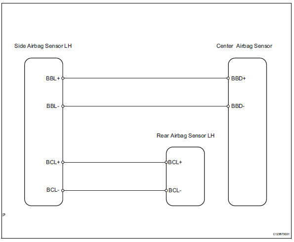
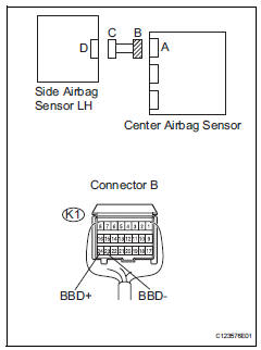
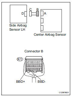
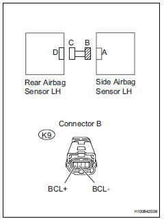
Wiring diagram
Inspection procedure
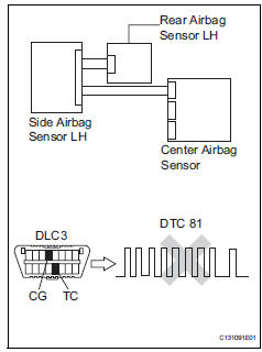
- Check for dtc
- Turn the ignition switch on, and wait for at least 60 seconds.
- Clear the dtcs (see page rs-49).
- Turn the ignition switch off.
- Turn the ignition switch on, and wait for at least 60 seconds.
- Check the dtcs (see page rs-49).
Ok: dtc b1622/81 is not output.
Dtc b1632/81 is not output.
Hint:
Dtcs other than dtc b1622/81 and b1632/81 may be output at this time, but they are not related to this check.

- Check connection of connector
- Turn the ignition switch off.
- Disconnect the cable from the negative (-) terminal battery, and wait for at least 90 seconds.
- Check that the connectors are properly connected to the center airbag sensor, rear airbag sensor lh and the side airbag sensor lh.
Ok: the connectors are properly connected.

- Check floor wire (open)
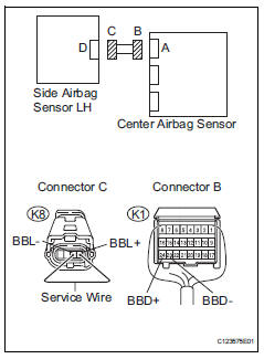
- Disconnect the connectors from the center airbag sensor and the side airbag sensor lh.
- Using a service wire, connect k8-4 (bbl+) and k8-3 (bbl-) of connector c.
Notice:
Do not forcibly insert the service wire into the terminals of the connector when connecting.
- Measure the resistance of the wire harness side connector.
Standard resistance


- Check floor wire (short)
- Disconnect the service wire from connector c.
- Measure the resistance of the wire harness side connector.
Standard resistance


- Check floor wire (to b+)
- Connect the cable to the negative (-) battery terminal, and wait for at least 2 seconds.
- Turn the ignition switch on.
- Measure the voltage of the wire harness side connector.
Standard voltage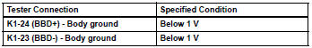


- Check floor wire (to ground)
- Turn the ignition switch off.
- Disconnect the cable from the negative (-) battery terminal, and wait for at least 90 seconds.
- Measure the resistance of the wire harness side connector.
Standard resistance 

- Check floor wire (open)
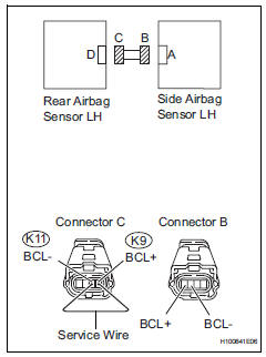
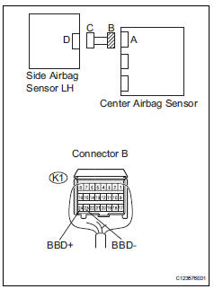
- Disconnect the connectors from the side airbag sensor lh and the rear airbag sensor lh.
- Using a service wire, connect k11-1 (bcl-) and k11-2 (bcl+) of connector c.
Notice:
Do not forcibly insert the service wire into the terminals of the connector when connecting.
- Measure the resistance of the wire harness side connector.
Standard resistance 

- Check floor wire (short)
- Disconnect the service wire from connector c.
- Measure the resistance of the wire harness side connector.
Standard resistance 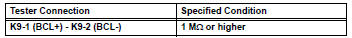

- Check floor wire (to b+)
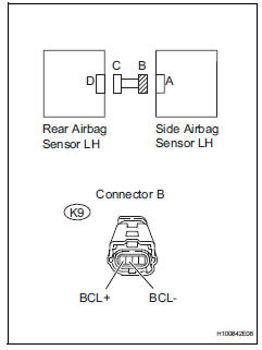
- Connect the cable to the negative (-) battery terminal, and wait for at least 2 seconds.
- Turn the ignition switch on.
- Measure the voltage of the wire harness side connector.
Standard voltage 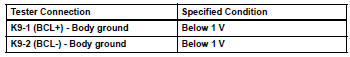


- Check floor wire (to ground)
- Turn the ignition switch off.
- Disconnect the cable from the negative (-) battery terminal, and wait for at least 90 seconds.
- Measure the resistance of the wire harness side connector.
Standard resistance 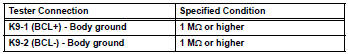


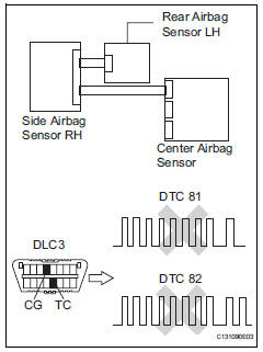
- Check side airbag sensor lh
- Connect the connectors to the center airbag sensor .
- Interchange the side airbag sensor lh with the side airbag sensor rh and connect the connectors to them.
- Connect the cable to the negative (-) battery terminal, and wait for at least 2 seconds.
- Turn the ignition switch on, and wait for at least 60 seconds.
- Clear the dtcs (see page rs-49).
- Turn the ignition switch off.
- Turn the ignition switch on, and wait for at least 60 seconds.
- Check the dtcs (see page rs-49).
Result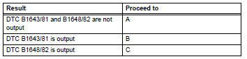
Hint:
Dtcs other than dtc b1643/81 and b1648/82 may be output at this time, but they are not related to this check.


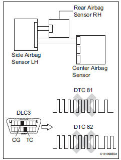
- Check rear airbag sensor lh
- Turn the ignition switch off.
- Disconnect the cable from the negative (-) terminal battery, and wait for at least 90 seconds.
- Interchange the rear airbag sensor lh with the rear airbag sensor rh and connect the connectors to them.
- Connect the cable to the negative (-) battery terminal, and wait for at least 2 seconds.
- Turn the ignition switch on, and wait for at least 60 seconds.
- Clear the dtcs (see page rs-49).
- Turn the ignition switch off.
- Turn the ignition switch on, and wait for at least 60 seconds.
- Check the dtcs (see page rs-49).
Result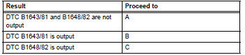
Hint:
Dtcs other than dtc b1643/81 and b1648/82 may be output at this time, but they are not related to this check.


Use simulation method to check
 Front passenger side rear airbag sensor circuit malfunction
Description
The rear airbag sensor rh consists of parts including the diagnostic circuit
and the lateral deceleration
sensor.
When the center airbag sensor receives signals from the lateral ...
 Front passenger side satellite sensor bus initialization incomplete
Description
When the center airbag sensor receives signals from the lateral deceleration
sensor, it determines
whether or not the srs should be activated.
Dtc b1648/82 is recorded when a ma ...
Other materials:
Air conditioning amplifier communication stop mode
Description
Wiring diagram
Inspection procedure
Notice:
Turn the ignition switch off before measuring the resistances
of the main wire and the branch
wire.
After the ignition switch is turned off, check that the key
reminder warning system and light
reminder warning sy ...
Safety information for children
Observe the following precautions when children are in the vehicle.
Use a child restraint system appropriate for the child, until the
child becomes large enough to properly wear the vehicle’s seat
belt.
It is recommended that children sit in the rear seats to avoid
accidental
contact ...
Oxygen (a/f) sensor pumping current circuit
Description
Refer to dtc p2195 (see page es-292).
Monitor description
The air-fuel ratio (a/f) sensor varies its output voltage in proportion to
the air-fuel ratio. If the a/f sensor
impedance (alternating current resistance) or output voltage deviates greatly
from the standard range ...
