Toyota RAV4 (XA40) 2013-2018 Service Manual: Ecm power source circuit
Description
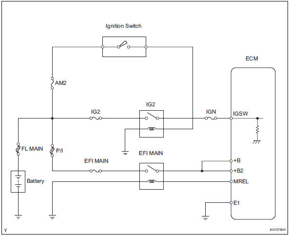
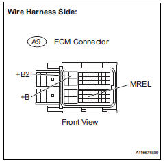
When the ignition switch is turned on, the battery voltage is applied to the igsw of the ecm. The output signal from the mrel terminal of the ecm causes a current to flow to the coil, closing the contacts of the integration relay (efi main relay) and supplying power to either terminal +b or +b2 of the ecm.
Wiring diagram
Inspection procedure
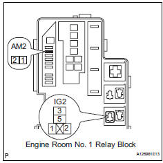
- Inspect fuses (p/i, am2, ig2, efi main, ign)
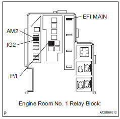
- Remove the p/i fuse, am2 fuse, ig2 fuse and efi main fuse from the engine room no. 1 Relay block.
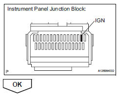
- Remove the ign fuse from the instrument panel junction block.
- Measure the resistance of the fuses.
Standard resistance: below 1

- Reinstall the fuses.
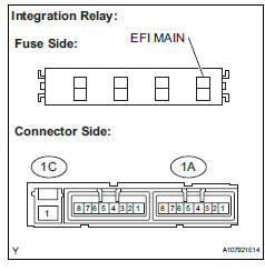
- Inspect relay (ig2, efi main)
- Remove the integration relay and ig2 relay from the engine room no. 1 Relay block.
- Measure the resistance between the terminal of the integration relay.
Standard resistance 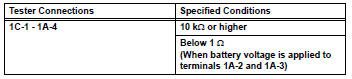
- Measure the resistance between the terminal of the ig2 relay.
Standard resistance 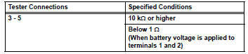
- Reinstall the relay.
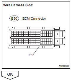
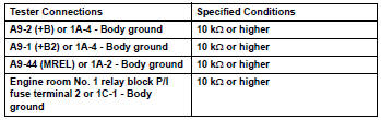
- Check harness and connector (ecm - body ground)
- Disconnect the b30 ecm connector.
- Measure the resistance.
Standard resistance 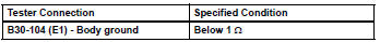
- Reconnect the ecm connector.
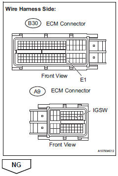
- Inspect ecm (igsw voltage)
- Disconnect the b30 and a9 ecm connectors.
- Turn the ignition switch on.
- Measure the voltage between the terminals of the b30 and a9 ecm connectors.
Standard voltage 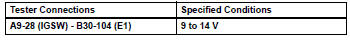
- Reconnect the ecm connector.

- Check harness and connector (relay block - ecm, ignition switch, battery)
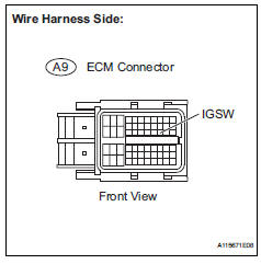
- Disconnect the a9 ecm connector.
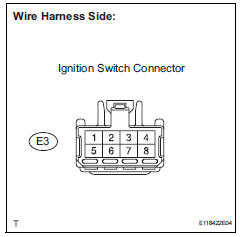
- Disconnect the e3 ignition switch connector.
- Disconnect the battery positive terminal.
- Remove the am2 fuse and ig2 relay.
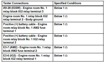
- Measure the resistance between the terminals.
Standard resistance (check for open)
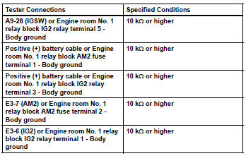
Standard resistance (check for short)
- Reinstall the relay and fuse.
- Reconnect the connectors.

- Inspect ignition switch (see page es-261)

- Check harness and connector (integration relay - ecm, battery, body ground)
- Disconnect the a9 ecm connector.
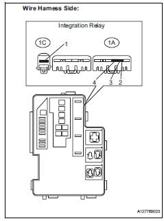
- Remove the integration relay from the engine room no. 1 Relay block.
- Disconnect the integration relay connector.
- Remove the p/i fuse from the engine room no. 1 Relay block.
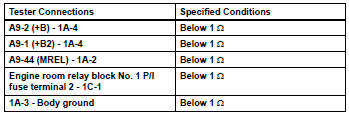
- Check the resistance between the terminals.
Standard resistance (check for open)
Standard resistance (check for short)
- Reconnect the connectors.
- Reinstall the integration relay and p/i fuse.
 Evap system
Related dtcs
If any evap system dtcs are set, the malfunctioning area can be determined
using the table below.
Notice:
If the reference pressure difference between the first and second ch ...
 Vc output circuit
Description
The ecm constantly generates 5 v power from the battery voltages supplied to
the +b (batt) terminal to
operate the microprocessor. The ecm also provides this power to the sensors
thr ...
Other materials:
Air conditioning amplifier communication stop mode
Description
Wiring diagram
Inspection procedure
Notice:
Turn the ignition switch off before measuring the resistances
of the main wire and the branch
wire.
After the ignition switch is turned off, check that the key
reminder warning system and light
reminder warning sy ...
Dtc check / clear
Check dtc
Hint:
When dtc b1650/23 is detected as a result of
troubleshooting for the airbag system, troubleshoot
the occupant classification system.
Use the intelligent tester (with can vim) to read and
clear dtcs, otherwise the dtcs cannot be read and
cleared.
Connect ...
Check for open circuit
For an open circuit in the wire harness in fig. 1,
Check the resistance or voltage, as described below.
Check the resistance.
Disconnect connectors a and c, and measure
the resistance between them.
Standard resistance (fig. 2)
Hint:
Measure the resistance while lightly s ...
