Toyota RAV4 (XA40) 2013-2018 Service Manual: Electronic control
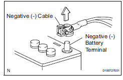
- Removal and installation of battery terminal
Notice:
Certain systems need to be initialized after disconnecting and reconnecting the cable from the negative (-) battery terminal.
- Before performing electronic work, disconnect the cable from the negative (-) battery terminal to prevent component and wire damage caused by accidental short circuits.
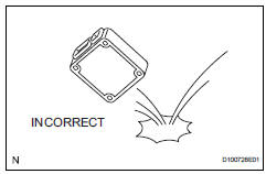
- When disconnecting the cable, turn the ignition switch off and headlight dimmer switch off and loosen the cable nut completely. Perform these operations without twisting or prying the cable. Then disconnect the cable.
- Clock settings, radio settings, audio system memory, dtcs and other data are erased when the cable is disconnected from the negative (-) battery terminal. Write down any necessary data before disconnecting the cable.
- Handling of electronic parts
- Do not open the cover or case of the ecu unless absolutely necessary. If the ic terminals are touched, the ic may be rendered inoperative by static electricity.
- Do not pull the wires when disconnecting electronic connectors. Pull the connector.
- Be careful not to drop electronic components, such as sensors or relays. If they are dropped on a hard surface, they should be replaced.
- When cleaning the engine with steam, protect the electronic components, air filter and emission-related components from water.
- Never use an impact wrench to remove or install temperature switches or temperature sensors.
- When measuring the resistance of a wire connector, insert the tester probe carefully to prevent terminals from bending.
 For vehicles with supplemental restraint system
The rav4 is equipped with a supplemental restraint
system (srs). The srs of this vehicle consists of the
following:
Steering pad
Front passenger airbag assembly
Front seat side airbag assemb ...
 Removal and installation of fuel control
parts
Removal and installation of fuel control
parts
Place for removing and installing fuel
system parts
Work in a location with good air ventilation that
does not have welders, grinders, drills, electric
motors, stoves, or any other igni ...
Other materials:
Reassembly
Install piston
Using a small screwdriver, install a new snap ring
onto one end of the piston pin hole.
Hint:
Make sure that the end gap of the snap ring is not
aligned with the pin hole cutout portion of the piston.
Gradually heat the piston up to 80 to 90°c (176 to
194°f ...
Removal
Disconnect cable from negative battery
terminal
Caution:
Wait at least 90 seconds after disconnecting the
cable from the negative (-) battery terminal to
prevent airbag and seat belt pretensioner activation.
Remove fan and generator v belt
Remove the belt (see page em-6).
...
Terminals of ecu
Check tire pressure warning ecu
Disconnect the e56 ecu connector.
Measure the voltage and resistance of the wire
harness side connector.
If the result is not as specified, there may be a
malfunction on the wire harness side.
Reconnect the e56 ecu connector.
Measure the ...
