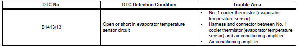
Toyota RAV4 (XA40) 2013-2018 Service Manual: Evaporator temperature sensor circuit
![]()
Description
The no. 1 Cooler thermistor (evaporator temperature sensor) is installed on the evaporator in the air conditioning unit to detect the temperature of the cooled air that has passed through the evaporator and to control the air conditioner. It sends signals to the air conditioning amplifier. The signals change in accordance with the resistance of the no. 1 Cooler thermistor (evaporator temperature sensor). As the temperature decreases, the resistance increases. As the temperature increases, the resistance decreases. The air conditioning amplifier applies a voltage (5 v) to the no. 1 Cooler thermistor (evaporator temperature sensor) and reads voltage changes as changes in the resistance of the no. 1 Cooler thermistor (evaporator temperature sensor). This sensor is used for frost prevention.
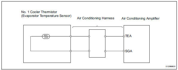
Wiring diagram
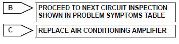
Inspection procedure
- Read value of intelligent tester (evap fin temp)
- Connect the intelligent tester (with can vim) to the dlc3.
- Turn the ignition switch on and turn the intelligent tester main switch on.
- Select the item below in the data list, and read the value displayed on the intelligent tester.
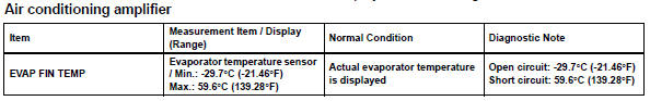
Ok: the display is as specified in the normal condition column.

- Inspect no. 1 Cooler thermistor (evaporator temperature sensor)
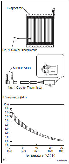
- Remove the no. 1 Cooler thermistor.
- Measure the resistance of the thermistor.
Standard resistance 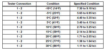
Notice:
- Touching the thermistor even slightly may change the resistance value. Be sure to hold the connector of the thermistor.
- When measuring, the thermistor temperature must be the same as the ambient temperature.
Hint:
As the temperature increases, the resistance decreases (see the graph).


Replace air conditioning harness assembly
 Ambient temperature sensor circuit
Description
The ambient temperature sensor is installed in the front part of the
condenser to detect the ambient
temperature and control the air conditioner. The sensor is connected to the
c ...
 Solar sensor circuit (passenger side)
Description
The solar sensor, which is installed on the upper side of the instrument
panel, detects sunlight and
controls the air conditioning auto mode. The output voltage from the solar
se ...
Other materials:
Seat belt pretensioners (front seats)
The pretensioners help the seat
belts to quickly restrain the occupants
by retracting the seat belts
when the vehicle is subjected to
certain types of severe frontal or
side collision or a vehicle rollover.
The pretensioners do not activate
in the event of a minor frontal
impact, a minor ...
Exhaust pipe
Components
Removal
Disconnect cable from negative battery terminal
Caution:
Wait at least 90 seconds after disconnecting the
cable from the negative (-) battery terminal to
prevent airbag and seat belt pretensioner activation.
Remove heated oxygen sensor (for bank 1
sensor 2) (s ...
Door control switch
Inspection
Inspect power window regulator master
switch assembly (door control switch)
Measure the resistance of the door control switch.
Standard resistance
If the result is not as specified, replace the power
window regulator master switch assembly.
Inspect door control s ...
