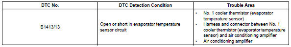
Toyota RAV4 (XA40) 2013-2018 Service Manual: Evaporator temperature sensor circuit
![]()
Description
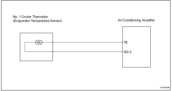
The no. 1 Cooler thermistor (evaporator temperature sensor) is installed on the evaporator in the air conditioning unit to detect the temperature of the cooled air that has passed through the evaporator and to control the air conditioner. It sends signals to the air conditioning amplifier. The signals change in accordance with the resistance of the no. 1 Cooler thermistor (evaporator temperature sensor). As the temperature decreases, the resistance increases. As the temperature increases, the resistance decreases. The air conditioning amplifier applies a voltage (5 v) to the no. 1 Cooler thermistor (evaporator temperature sensor) and reads voltage changes as changes in the resistance of the no. 1 Cooler thermistor (evaporator temperature sensor). This sensor is used for frost prevention.
Wiring diagram
Inspection procedure
- Read value of intelligent tester (evap fin temp)
- Connect the intelligent tester (with can vim) to the dlc3.
- Turn the ignition switch on and turn the intelligent tester main switch on.
- Select the item below in the data list, and read the value displayed on the intelligent tester.
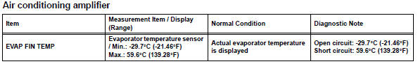
Ok: the display is as specified in the normal condition column.

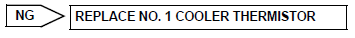
- Inspect no. 1 Cooler thermistor (evaporator temperature sensor)
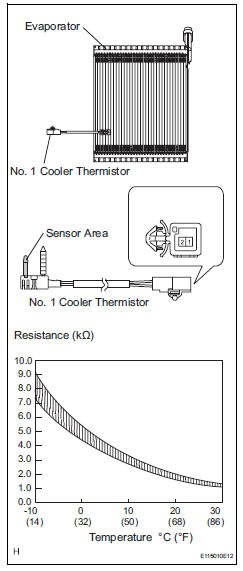
- Remove the no. 1 Cooler thermistor.
- Measure the resistance of the thermistor.
Standard resistance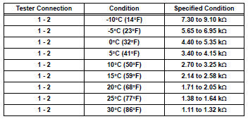
Notice:
- Touching the thermistor even slightly may change the resistance value. Be sure to hold the connector of the thermistor.
- When measuring, the thermistor temperature must be the same as the ambient temperature.
Hint:
As the temperature increases, the resistance decreases (see the graph).

- Check wire harness (no. 1 Cooler thermistor - air conditioning amplifier)
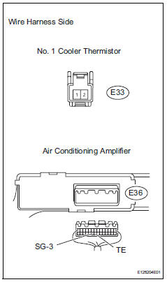
- Disconnect the e33 no. 1 Cooler thermistor connector.
- Disconnect the e36 amplifier connector.
- Measure the resistance of the wire harness side connectors.
Standard resistance 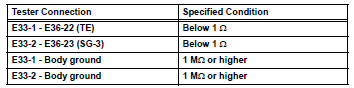

Replace air conditioning amplifier
 Ambient temperature sensor circuit
Description
The ambient temperature sensor is installed in the front part of the
condenser to detect the ambient
temperature and control the air conditioner. The sensor is connected to the
c ...
 Compressor lock sensor circuit
Description
This sensor sends 1 pulse per engine revolution to the air conditioning
amplifier. If the ratio of the
compressor speed divided by the engine speed is smaller than a predetermined ...
Other materials:
Diagnostic trouble code chart (2006/01- )
Hint:
When the air conditioning system functions properly, dtc
b1400/00 is output.
Hint:
*1: Dtc b1422/22 (compressor lock sensor circuit) is
indicated only for a currently occurring malfunction for 2grfe.
To confirm dtc b1422/22, perform the following steps:
With the ignition swit ...
List screen operation
When a list screen is displayed, use the appropriate buttons to
scroll through the list.
How to scroll
Select to scroll to the next
or previous page.
Appears to the right of
titles, the complete titles are
too long for the display. Select
this button to scroll the title.
Turn th ...
Back-up power source circuit
Description
This is the back-up power source circuit for the air conditioning amplifier.
Power is supplied even when the
ignition switch is turned off and is used for functions such as the diagnostic
trouble code memory.
wiring diagram
Inspection procedure
Inspect fuse (ecu-b2)
...
