Toyota RAV4 (XA40) 2013-2018 Service Manual: Footwell light circuit
Description
The main body ecu receives information regarding the door lock position switch and ignition switch, and turns on each foot light.
Wiring diagram
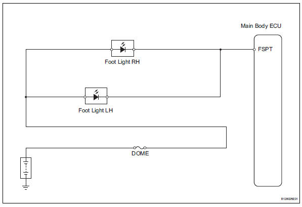
Inspection procedure
- Perform active test by intelligent tester (main body ecu)
- Connect the intelligent tester (with can vim) to the dlc3.
- Turn the ignition switch to the on position and press the intelligent tester main switch on
- Select the items below in the active test and then check the relay operation.

Ok: light comes on.

- Inspect fuse (dome)
- Remove the dome fuse from the engine room no. 2 Relay block.
- Measure the resistance of the fuse.
Standard resistance:
below 1 


- Inspect foot light
- Remove the foot light.
- Connect the positive (+) lead from the battery to terminal 2 and the negative (-) lead to terminal 1, then check that the light comes on.
Ok: light comes on.

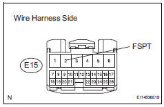
- Check wire harness (battery - main body ecu)
- Install the foot light.
- Disconnect the e15 main body ecu connector.
- Measure the voltage of the wire harness side connector.
Standard voltage 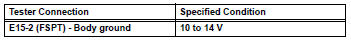

Replace instrument panel junction block (main body ecu)
 Door lock position circuit
Description
This circuit detects the state of the door lock detection sensor and sends it
to the main body ecu.
Wiring diagram
Inspection procedure
Read value of intelligent tester (door ...
 Illumination circuit
Description
The main body ecu receives information regarding the door courtesy switch and
door lock position
switch, and turns on the room light.
Wiring diagram
Inspection procedure
Perf ...
Other materials:
Transponder chip malfunction
Description
This dtc is output when: 1) during key code registration, a key malfunction
occurs; 2) the key code was
unable to be registered properly.
Inspection procedure
Reregister key
Clear the dtc (see page ei-18).
Reregister the key code with the transponder key ecu
(s ...
For your information
Main owner’s manual
Please note that this manual applies to all models and all equipment,
including
options. Therefore, you may find some explanations for equipment not
installed on your vehicle.
All specifications provided in this manual are current at the time of printing.
However, be ...
Removal
Hint:
Use the same procedures for the rh side and lh side.
The procedures listed below are for the lh side.
Disconnect cable from negative battery terminal
Notice:
Wait at least 90 seconds after disconnecting the
cable from the negative (-) battery terminal to
prevent airbag and se ...
