Toyota RAV4 (XA40) 2013-2018 Service Manual: Headlight (hi-beam) circuit
Description
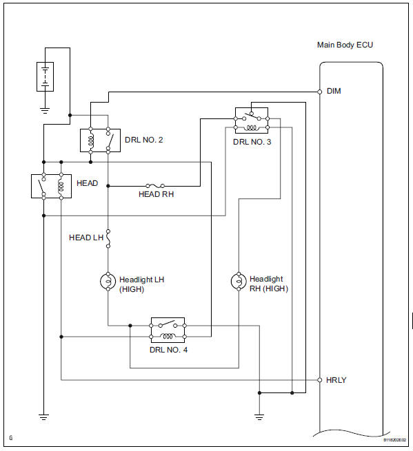
The body ecu controls the headlight relay, no. 2 Daytime running light relay (marking: drl no. 2) And no. 4 Daytime running light relay (marking: drl no. 4).
Wiring diagram
Inspection procedure
- Perform active test by intelligent tester
- Connect the intelligent tester (with can vim) to the dlc3.
- Turn the ignition switch to the on position and press the intelligent tester main switch on.
- Select the item below in the active test and then check the relay operation.
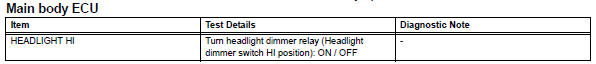
Ok: headlight (high) comes on.

- Check headlight (low)
- Check that the headlight (low) comes on when the light control switch is on (head).
Ok: headlight (low) comes on.

- Inspect fuse (head lh, head rh)
- Remove the head lh fuse and head rh fuse from the engine room no. 2 Relay block.
- Measure the resistance of the fuses.
Standard resistance:
below 1 

- Inspect daytime running light relay (marking: drl no. 2, Drl no. 3, Drl no. 4)
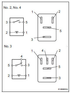
- Remove the no. 2 Relay, no. 3 Relay and no. 4 Relay from the engine room no. 2 Relay block.
- Measure the resistance of the relays.
Standard resistance:
No. 2, No. 4 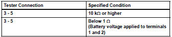
No. 3 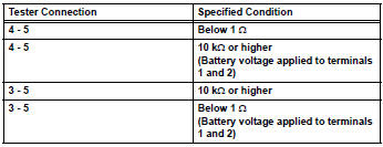

- Inspect headlight bulb (high)
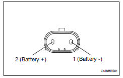
- Remove the headlight bulb (high).
- Connect the positive (+) lead from the battery to terminal 2 and the negative (-) lead to terminal 1, then check that the bulb illuminates.

- Check wire harness (main body ecu - battery)
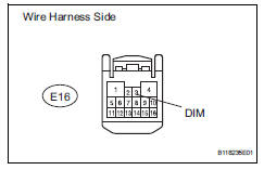
- Disconnect the e16 main body ecu connector.
- Measure the voltage of the wire harness side connector.
Standard voltage 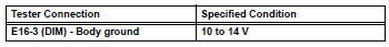

- Check wire harness (main body ecu)
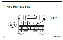
- Remove the headlight relay from the engine room no. 2 Relay block.
- Disconnect the e15 main body ecu connector.
- Measure the voltage of the wire harness side connector.
Standard voltage 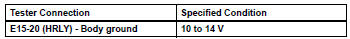

- Check wire harness (headlight relay - no. 3 Daytime running light relay and body ground)
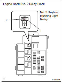
- Remove the no. 3 Daytime running light relay from the engine room no. 2 Relay block.
- Measure the voltage and resistance of the relay block.
Standard voltage 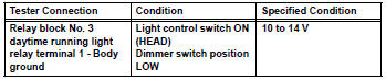
Standard resistance 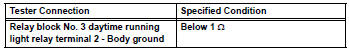

- Check wire harness (battery - no. 2 Daytime running light relay, bulb and body ground)
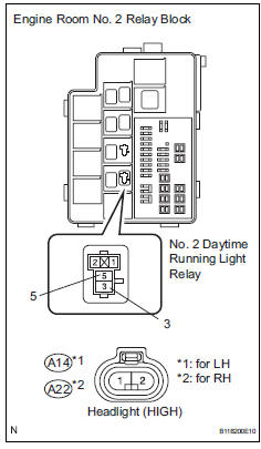
- Remove the no. 2 Daytime running light relay from the engine room no. 2 Relay block.
- Remove the a14 and a22 headlight bulb connectors.
- Measure the voltage and resistance of the relay block.
Standard voltage 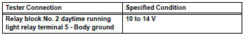
Standard resistance 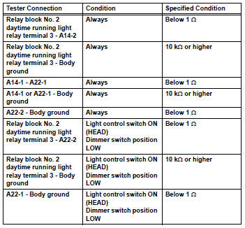

Replace instrument panel junction block (main body ecu)
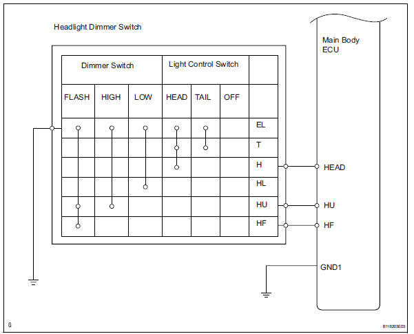
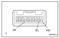
- Check wire harness (main body ecu - dimmer switch)
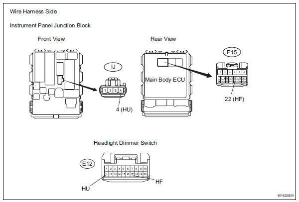
- Disconnect the e15 main body ecu connector.
- Disconnect the e12 headlight dimmer switch connector.
- Disconnect the ij instrument panel junction block connector.
- Measure the resistance of the wire harness side connectors.
Standard resistance 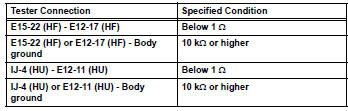

- Inspect headlight dimmer switch
- Remove the headlight dimmer switch.
- Measure the resistance of the switch.
Standard resistance 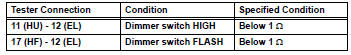

Repair or replace harness and connector (headlight dimmer switch - body ground)
 Drl relay circuit
Description
The main body ecu controls the daytime running light no. 2 Relay (marking:
drl no.2).
Wiring diagram
Inspection procedure
Inspect daytime running light relay (marking: drl no. ...
 Front fog light circuit
Description
The main body ecu controls the front fog light relay (marking: fr fog) when a
signal is received from
the headlight dimmer switch.
Wiring diagram
Inspection procedure
Perform ...
Other materials:
Precaution
Check that the battery cables are connected to the
correct terminals.
Disconnect the battery cables if a quick charge is
given to the battery.
Do not perform tests with a high voltage insulation
resistance tester.
Never disconnect the battery while the engine is
running.
Check tha ...
Reassembly
V
Attach the 7 outside moulding retainers to install the
extension.
Install front bumper extension rh (for wide
body)
Hint:
Use the same procedures described for the lh side.
Install front bumper hole cover lh (w/o fog
light)
Install the bumper hole cover with ...
On-vehicle inspection
Notice:
Perform the maf meter inspection according to the
procedures below.
Only replace the maf meter when both the long
ft#1 value and maf value in the data list (with the
engine stopped) are not within the normal operating
range.
Inspect mass air flow meter
Perform c ...
