Toyota RAV4 (XA40) 2013-2018 Service Manual: Horn system
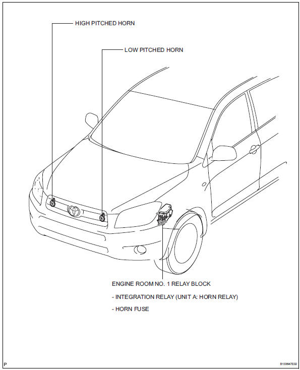
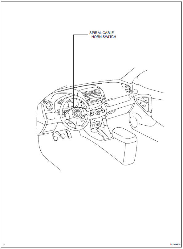
Parts location
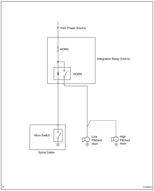
System diagram
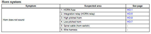
Problem symptoms table
Hint:
Use the table below to help determine the cause of the problem symptom. The potential causes of the symptoms are listed in order of probability in the "suspected area" column of the table. Check each symptom by checking the suspected areas in the order they are listed. Replace parts as necessary.
 Horn
Horn
...
 Horn relay
On-vehicle inspection
Remove engine room no. 1 Relay block cover
Inspect integration relay (unit a: horn relay)
Using a screwdriver, detach the 2 claws and
disconnect the integration ...
Other materials:
On-vehicle inspection
Check ignition coil assembly and perform spark test
Notice:
in this section, the terms "cold" and "hot" refer to
the temperature of the coils. "Cold" means
approximately -10 to 50°c (14 to 122°f). "Hot" means
approximately 50 to 100°c (122 to 212 ...
Wheels
If a wheel is bent, cracked or heavily corroded, it should be
replaced. Otherwise, the tire may separate from the wheel or
cause a loss of handling control.
Wheel selection
When replacing wheels, care should be taken to ensure that they are
equivalent to those removed in load capacity, diameter ...
Diagnosis system
Diagnosis
If the skid control ecu detects a malfunction, the abs,
vsc and brake warning lights and the slip, downhill
assist control and auto lsd indicator lights come on in
accordance with the trouble area to warn the driver.
The table below indicates which lights come on when
there ar ...
