Toyota RAV4 (XA40) 2013-2018 Service Manual: How to proceed with troubleshooting
Notice:
- Dtcs for the can communication system are as follows: u0073, u0100, u0105, u0121, u0122, u0123, u0124, u0126, u0129, c1280, c1296, c1297, and b1499.
- Refer to the troubleshooting procedures of each system if dtcs regarding the can communication system are not output.
- Turn the ignition switch off before measuring the resistances of the main wire and the branch wire.
- After the ignition switch is turned off, check that the key reminder warning system and light reminder warning system are not in operation.
- Before measuring the resistance, leave the vehicle for at least 1 minute and do not operate the ignition switch, any switches or doors. If doors need to be opened in order to check connectors, open the doors and leave them open.
Hint:
- *: Use the intelligent tester (with can vim).
- Operating the ignition switch, any switches or any doors triggers related ecu and sensor communication with the can, which causes resistance variation.
- Vehicle brought to workshop

- Inspect battery voltage
Standard voltage:: 11 to 14 v
If the voltage is below 11 v, recharge or replace the battery before proceeding.

- Check can bus line
- Check the can bus line (see page ca-75).

- Check installed systems (ecu and sensor) that use can communication

- Check and clear dtc*

- Check intelligent tester via can vim*
- Select "communication bus check" (see page ca- 34).
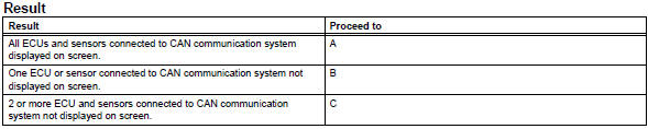
Notice:
- The systems (ecus and sensors) that use can communication vary depending on the vehicle and option settings. Check which systems (ecus and sensors) are installed on the vehicle (see page ca-34).
- Non-installed ecus or sensors are not displayed. Do not mistake them for being in communication stop mode
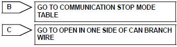
- If 2 or more ecus or sensors are not displayed on the intelligent tester, perform troubleshooting for open circuits in one side of the can branch line for each undisplayed ecu or sensor.

- Dtc combination table
- Confirm the trouble according to the combination of output dtcs regarding the can communication system.
Hint:
Previous can communication system dtcs may be the cause if can communication system dtcs are output and all ecus and sensors connected to the can communication system are displayed on the intelligent tester "communication bus check" screen.
- Check the dtc combination table (see page ca-34).

- Circuit inspection

- Identify problem

- Repair or replace

- Confirmation test

End
 System description
Brief description
The can (controller area network) is a serial data
communication system for real time application. It is
a vehicle multiplex communication system which
has a high comm ...
 Problem symptoms table
(2005/11-2006/01)
(2006/01- )
Hint:
*: For 4wd ...
Other materials:
On-vehicle inspection
Check driver side seat belt warning light
Turn the ignition switch on.
When the driver side seat belt is not fastened, check
that the combination meter's driver side seat belt
warning light starts blinking.
When the seat belt is fastened, check that the
combination meter's driver ...
Reassembly (2005/11-2006/01)
Install drive shaft bearing case subassembly
Using sst and a press, press in the drive shaft
bearing case to the inboard joint rh.
Sst 09527-10011, 09710-04081
Notice:
The bearing should be installed completely.
Using a snap ring expander, install a new drive shaft
hole ...
Installation
Hint:
Use the same procedures for the lh side and rh side.
The procedures listed below are for the lh side.
A bolt without a torque specification is shown in the
standard bolt chart (see page ss-2).
Install front shoulder belt anchor adjuster assembly
Align the adjuster pos ...
