Toyota RAV4 (XA40) 2013-2018 Service Manual: Ignition key cylinder light
Components
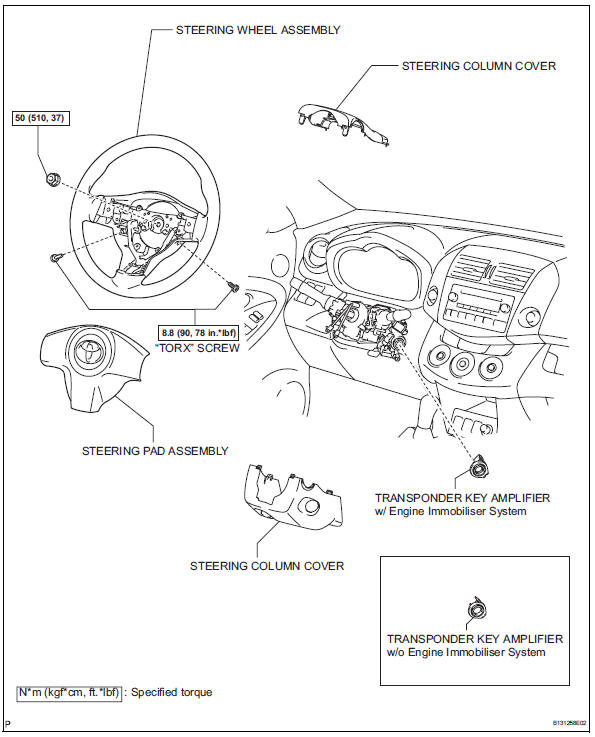
Removal
- Disconnect cable from negative battery
Caution:
Wait at least 90 seconds after disconnecting the cable from the negative (-) battery terminal to prevent airbag and seat belt pretensioner activation.
- Place front wheels facing straight ahead
- Remove steering pad assembly (see page rs- 336)
- Remove steering wheel assembly (see page sr-12)
- Remove steering column cover (see page sr-12)
- Remove transponder key amplifier (see page sr-14)
Inspection
- Inspect transponder key amplifier
- W/ engine immobiliser system:
Connect the battery's positive (+) lead to terminal 2 and the negative (-) lead to terminal 6, and then check that the light comes on.
Ok: led illuminates.
If the result is not as specified, replace the transponder key amplifier.
- W/o engine immobiliser system:
- Connect the battery's positive (+) lead to terminal 2 and the negative (-) lead to terminal 1, and then check that the light comes on.
Ok: led illuminates.
If the result is not as specified, replace the transponder key amplifier.
Installation
- Install transponder key amplifier (see page sr-18)
- Install steering column cover (see page sr- 20)
- Install steering wheel assembly (see page sr-21)
- Place front wheels facing straight ahead
- Inspect steering wheel center point
- Install steering pad assembly (see page rs- 336)
- Connect cable to negative battery terminal
- Inspect steering pad assembly (see page rs- 337)
- Check srs warning light
- Check the srs warning light (see page rs-337).
 Luggage room light
Components
Removal
Disconnect cable from negative battery
terminal
Caution:
Wait at least 90 seconds after disconnecting the
cable from the negative (-) battery terminal to
prevent ai ...
 Vanity light
Components
Removal
Hint:
Use the same procedures for the rh and lh sides.
The procedures listed below are for the lh side.
Disconnect cable from negative battery
terminal
Cautio ...
Other materials:
Problem symptoms table (2006/01- )
Hint:
Use the table below to help determine the cause of the
problem symptom. The potential causes of the symptoms are
listed in order of probability in the "suspected area" column
of the table. Check each symptom by checking the suspected
areas in the order they are listed. Replace p ...
Air-fuel ratio (a/f) and heated oxygen (ho2) sensor
heater monitors (front a/f and rear ho2 sensor type)
Preconditions
The monitor will not run unless:
The mil is off.
Drive pattern
Connect the intelligent tester to the dlc3.
Turn the ignition switch on.
Turn the tester on.
Clear dtcs (if set) (see page es-35).
Start the engine.
Allow the engine to idle for 10 minute ...
Intermediate shaft speed sensor "A"
Description
This sensor detects the rotation speed of the counter gear. By comparing the
counter gear speed signal
(nc) with the direct clutch speed sensor signal (nt), the ecm detects the shift
timing of the gears and
approximately controls the engine torque and hydraulic pressure accord ...
