Toyota RAV4 (XA40) 2013-2018 Service Manual: Installation
- Install upper instrument panel
- Attach the 6 clips and 5 claws to install the instrument panel.
- Connect the connectors and clamps.
- Install the 2 bolts and 2 screws.
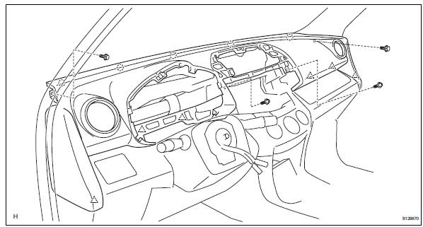
- Connect the passenger airbag connector.
- Install the 2 bolts to the passenger airbag.
Torque: 20 n*m (204 kgf*cm, 15 ft.*Lbf)
- Install front pillar garnish lh (see page ir- 57)
- Install front pillar garnish rh (see page ir- 58)
- Install glove compartment door assembly (see page ip-25)
- Install instrument panel register assembly center
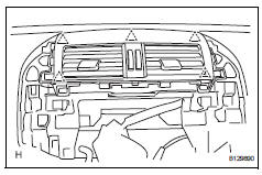
- Attach the 5 clips to install the instrument panel register.
- Install radio receiver
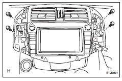
- Connect the connectors.
- Attach the 4 clips to install the radio receiver.
- Install the 4 bolts.
- Install no. 1 Instrument cluster finish panel center
- Connect the connector.
- Attach the 3 clips and 3 claws to install the cluster finish panel.
- Install no. 2 Instrument cluster finish panel center
- Connect the connector.
- Attach the 3 clips and 3 claws to install the cluster finish panel.
- Install combination meter assembly
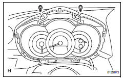
- Connect the connector.
- Attach the 2 clips to install the combination meter.
- Install the 2 screws.
- Install instrument cluster finish panel sub-assembly
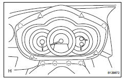
- Attach the 4 clips and 6 claws to install the instrument cluster finish panel.
- Connect cable to negative battery terminal
- Check srs warning light
- Check the srs warning light (see page rs-37).
 Reassembly
Install cooler (solar sensor) thermistor
(for automatic air conditioning system)
Install automatic light control sensor
(for automatic light control system)
Install front passenger airbag a ...
 Lower instrument panel
Precaution
Precaution for vehicle with srs airbag and
seat belt pretensioner
Some operations in this section may affect the srs
airbags and seat belt pretensioner. Prior to
performing ...
Other materials:
Oxygen (a/f) sensor heater control circuit
Hint:
Although the dtc titles say oxygen sensor, these dtcs relate to the
air-fuel ratio (a/f) sensor.
Sensor 1 refers to the sensor mounted in front of the three-way
catalytic converter (twc) and
located near the engine assembly.
Description
Refer to dtc p2195 (see page es-292 ...
Reassembly
Install generator rotor assembly
Install the washer onto the generator rectifier end
frame.
Install the generator rotor onto the generator
rectifier end frame.
Using a 32 mm socket wrench and press, slowly
push the generator drive end frame onto the
generator ...
If your vehicle has to be stopped in an emergency
Only in an emergency, such
as if it becomes impossible
to stop the vehicle in the
normal way, stop the vehicle
using the following procedure:
Stopping the vehicle
1. Steadily step on the brake
pedal with both feet and
firmly depress it.
Do not pump the brake pedal
repeatedly as this will increase t ...
