Toyota RAV4 (XA40) 2013-2018 Service Manual: Installation (2005/11-2006/01)
- Install front drive shaft assembly lh
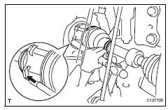
- Coat the spline of the inboard joint shaft with gear oil.
- Using a brass bar and hammer, align the shaft splines in the drive shaft.
Notice:
- Set the snap ring with the opening side facing downwards.
- Be careful not to damage the oil seal, boot and dust cover.
- Install front drive shaft assembly rh
- Coat the spline of the inboard joint shaft with gear oil.
- Align the shaft splines and securely insert the drive shaft.
Notice:
Do not damage the oil seal.
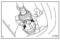
- Squeeze the ends of the bracket hole snap ring and install it to the bearing bracket.
- Install the bearing bracket bolt torque: 32.4 N*m (330 kgf*cm, 24 ft.*Lbf)
- Connect steering knuckle with axle hub lh
- Align the shaft splines in the drive shaft to the steering knuckle with axle hub.
- Connect steering knuckle with axle hub rh
Hint:
Use the same procedures described for lh side.
- Connect front suspension lower no. 1 Arm sub-assembly lh (see page ah-10)
- Connect front suspension lower no. 1 Arm sub-assembly rh
Hint:
Use the same procedures described for lh side.
- Install front stabilizer link assembly lh (see page sp-31)
- Install front stabilizer link assembly rh
Hint:
Use the same procedures described for lh side.
- Install tie rod end sub-assembly lh (see page ps-45)
- Install tie rod end sub-assembly rh
Hint:
Use the same procedures described for lh side.
- Connect front speed sensor lh
- Connect the speed sensor (see page bc-193).
- Connect front speed sensor rh
Hint:
Use the same procedures described for the lh side.
- Install front axle hub nut (see page ah-10)
- Install front wheel torque: 103 n*m (1,050 kgf*cm, 76 ft.*Lbf)
- Add automatic transaxle fluid
- Add automatic transaxle fluid for u140f (see page ax-152).
- Add automatic transaxle fluid for u241e (see page ax-151).
- Check for automatic transaxle fluid leakage
- Inspect and adjust front wheel alignment
- Inspect and adjust front wheel alignment (see page sp-3).
 Reassembly (2006/01- )
Install front drive shaft bearing (for rh)
Install the bearing bracket snap ring to the inboard
shaft.
Using sst and a press, press in the drive shaft
bearing to the inboard joint r ...
 Installation (2006/01- )
Install front drive shaft assembly lh
Coat the spline of the inboard joint shaft with gear
oil.
Align the shaft splines and tap in the drive shaft with
a brass bar and hammer.
No ...
Other materials:
General maintenance (2006/01- )
Inspect steering linkage and gear housing
Check the steering wheel free play.
Check the steering linkage for looseness or
damage.
Check that the tie rod ends do not have
excessive play.
Check that the dust seals and boots are not
damaged.
Check that the boot clamps are not ...
Data list / active test
Read data list
Hint:
Using the intelligent tester's data list allows switch,
actuator and other item values to be read without
removing any parts. Reading the data list early in
troubleshooting is one way to save time.
Connect the intelligent tester (with can vim) to the
dlc3.
Turn ...
Speed sensor
Components
Removal
Disconnect cable from negative battery
terminal
Caution:
Wait at least 90 seconds after disconnecting the
cable from the negative (-) battery terminal to
prevent airbag and seat belt pretensioner activation.
Remove battery
Loosen the nut and remove the b ...
