Toyota RAV4 (XA40) 2013-2018 Service Manual: Intermediate shaft speed sensor "A"
![]()
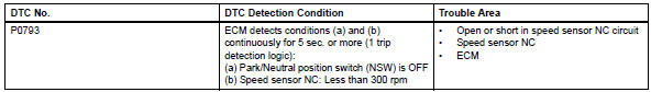
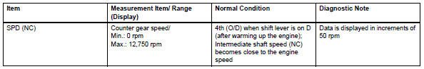
Description
This sensor detects the rotation speed of the counter gear. By comparing the counter gear speed signal (nc) with the direct clutch speed sensor signal (nt), the ecm detects the shift timing of the gears and approximately controls the engine torque and hydraulic pressure according to various conditions. Thus smooth gear shifting is performed.
Monitor description
The nc terminal of the ecm detects revolution signals from speed sensor nc (counter gear rpm). The ecm calculates gear shifts by comparing speed sensor nt with speed sensor nc.
While the vehicle is operating in the 2nd, 3rd or o/d gear position with the shift lever on d, if the counter gear revolution is less than 300 rpm*1 and the output shaft revolution is more than 1,000 rpm*2, the ecm detects the trouble, illuminates the mil and stores the dtc.
*1: Pulse is not output or is irregularly output.
*2: The vehicle speed is 50 km/h (31 mph) or more.
Monitor strategy
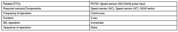
Typical enabling conditions
Typical malfunction thresholds
![]()
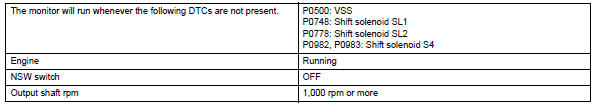
Component operating range
![]()
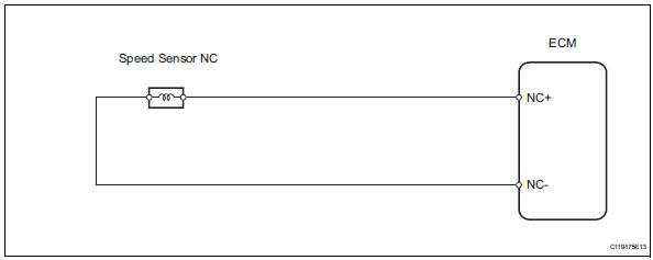
Wiring diagram
Inspection procedure
Hint:
Using the intelligent tester's data list allows switch, sensor, actuator and other item values to be read without removing any parts. Reading the data list early in troubleshooting is one way to save time.
Notice:
In the table below, the values listed under "normal condition" are reference values. Do not depend solely on these reference values when deciding whether a part is faulty or not.
- Warm up the engine.
- Turn the ignition switch off.
- Connect the intelligent tester to the can vim. Then connect the can vim to the dlc3.
- Turn the ignition switch on and turn the tester on.
- Enter the following menus: diagnosis / enhanced obd ii / data list.
- Follow the instructions on the tester and read the data list.
Hint:
- Spd (nc) is always 0 rpm while driving: open or short in the sensor or circuit.
- Spd (nc) is always more than 0 and less than 300 rpm while driving the vehicle at 50 km/h (31 mph) or more: sensor trouble, improper installation, or intermittent connection trouble of the circuit.
- Inspect speed sensor (installation)
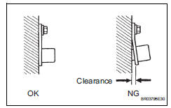
- Check the speed sensor nc installation.
Ok: installation bolt is tightened properly and there is no clearance between the sensor and transaxle case.

- Inspect speed sensor nc
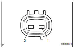
- Disconnect the b24 sensor connector from the transaxle.
- Measure the resistance of the sensor.
Standard resistance 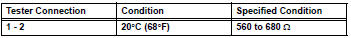

- Check wire harness (speed sensor - ecm)
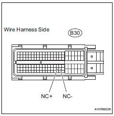
- Disconnect the b30 ecm connector.
- Measure the resistance of the wire harness side connector.
Standard resistance 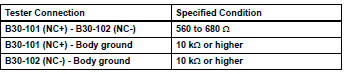

Replace ecm
 Pressure control solenoid "b" electrical (shift solenoid valve sl2)
Description
Shifting from 1st to o/d is performed in combination with the on and off
operation of the shift solenoid
valves sl1 and sl2, which are controlled by the ecm. If an open or short ci ...
 Shift solenoid "d" control circuit
Description
Shifting from 1st to o/d is performed in combination with the on and off
operation of the shift solenoid
valves sl1 and sl2, which are controlled by the ecm. If an open or short ci ...
Other materials:
Removal
Disconnect cable from negative battery
terminal
Caution:
Wait at least 90 seconds after disconnecting the
cable from the negative (-) battery terminal to
prevent airbag and seat belt pretensioner activation.
Remove no. 1 Engine cover (see page es-410)
Remove camshaft timing oil cont ...
Fuel system
Precaution
Before working on fuel system
Do not work near an open flame.
Keep gasoline away from rubber and leather parts.
Discharge the fuel pressure before disconnecting
the fuel line to prevent gasoline from spilling out.
Refer to the following procedure.
Discharge fuel ...
Detailed bluetoothÂź
system settings
You can confirm and change the detailed bluetoothÂź settings.
How to check and change detailed bluetoothÂź settings
Display the âbluetooth* setupâ screen.
Select âsystem settingsâ.
The following screen is displayed:
BluetoothÂź power on/off. You can change bluetoothÂź
fu ...
