Toyota RAV4 (XA40) 2013-2018 Service Manual: Internal control module random access memory (ram) error
Description
The ecm continuously monitors its own internal memory status, internal circuits, and output signals transmitted to the throttle actuator. This self-check ensures that the ecm is functioning properly. If any malfunction is detected, the ecm sets the appropriate dtc and illuminates the mil.
The ecm memory status is diagnosed by internal mirroring of the main cpu and the sub cpu to detect random access memory (ram) errors. The two cpus also perform continuous mutual monitoring. The ecm illuminates the mil and sets a dtc if: 1) outputs from the two cpus are different or deviate from the standards, 2) the signals sent to the throttle actuator deviate from the standards, 3) a malfunction is found in the throttle actuator supply voltage, and 4) any other ecm malfunction is found.

Monitor strategy
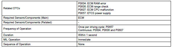
Typical enabling conditions
![]()
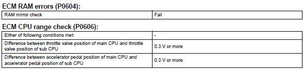
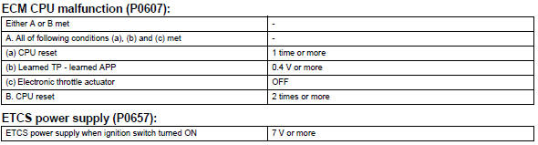
Typical malfunction thresholds
Inspection procedure
Read freeze frame data using the intelligent tester. Freeze frame data records the engine condition when malfunctions are detected. When troubleshooting, freeze frame data can help determine if the vehicle was moving or stationary, if the engine was warmed up or not, if the air-fuel ratio was lean or rich, and other data from the time the malfunction occurred.
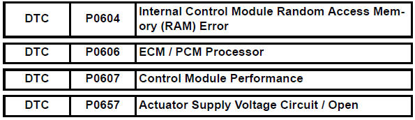
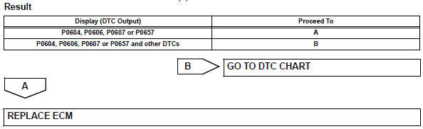
- Check any other dtcs output (in addition to dtc p0604, p0606, p0607 or p0657)
- Connect the intelligent tester to the dlc3.
- Turn the ignition switch on.
- Turn the tester on.
- Select the following menu items: diagnosis / enhanced obd ii / dtc info / current codes.
- Read dtcs.
 System voltage
Description
The battery supplies electricity to the ecm even when the ignition switch is
in the off position. This
power allows the ecm to store data such as dtc history, freeze frame data and ...
 Starter relay circuit high
Description
While the engine is being cranked, the positive battery voltage is applied to
terminal sta of the ecm. If
the ecm detects the starter control (sta) signal while the vehicle is bein ...
Other materials:
The keys
The following keys are provided with the vehicle.
Vehicles without a smart key system (type a)
Master keys
Operating the wireless remote control
function
Valet key
Key number plate
Vehicles without a smart key system (type b)
Master keys
Operating the wireless r ...
Disassembly
Caution:
Wear protective gloves. Sharp areas on the seat frame
(with adjuster) may injure your hands.
Remove reclining power seat switch knob
Using a screwdriver, detach the knob.
Hint:
Tape the screwdriver tip before use.
Remove slide and vertical power seat switch knob
...
Panoramic moon roof
Use the overhead switches
to operate the panoramic
moon roof and electronic
sunshade.
Operating the electronic
sunshade and panoramic
moon roof
‚Ė† Opening and closing the
electronic sunshade
Opens the electronic sunshade*
Slide and hold the switch
backward. The electronic sunshade
will fully ...
