Toyota RAV4 (XA40) 2013-2018 Service Manual: Key reminder warning system
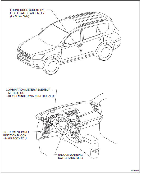
Parts location
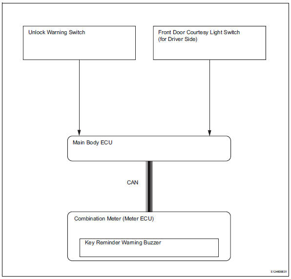
System diagram
- System description
- How to proceed with troubleshooting
- Operation check
- Problem symptoms table
- Terminals of ecu
- Diagnosis system
- Data list / active test
 Key lock-in prevention function does not work properly
Description
When the key is in the ignition key cylinder or the door courtesy light on
signal is output to the main body
ecu, performing the door lock operation with the lock switch does not lock ...
 System description
Key reminder warning system description
When the driver side door is opened with the key in
the ignition key cylinder and ignition switch in the
acc or off position, this system causes th ...
Other materials:
How to proceed with troubleshooting
Hint:
Use the procedure to troubleshoot the power door lock
control system.
*: Use the intelligent tester.
Vehicle brought to workshop
Inspect battery voltage
Standard voltage:
11 to 14 v
If the voltage is below 11 v, recharge or replace the battery
before proceeding.
...
If your vehicle needs to be
towed
If towing is necessary, we
recommend having your
vehicle towed by your
Toyota dealer or commercial
towing service, using a
wheel-lift type truck or flatbed
truck.
Use a safety chain system
for all towing, and abide by
all state/provincial and local
laws.
Situations when it is necessary
to contact d ...
Pressure control solenoid "d" electrical (shift solenoid valve slt)
Description
Refer to dtc p2714 (see page ax-91).
Monitor description
When an open or short in the shift solenoid valve slt circuit is detected,
the ecm interprets this as a fault.
The ecm will illuminate the mil and store the dtc.
Monitor strategy
Typical enabling conditions
...
