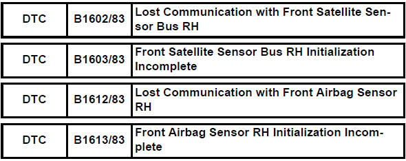
Toyota RAV4 (XA40) 2013-2018 Service Manual: Lost communication with front satellite sensor bus rh
Description
The front airbag sensor rh consists of the diagnostic circuit and the frontal deceleration sensor.
If the center airbag sensor receives signals from the frontal deceleration sensor, it determines whether or not the srs should be activated.
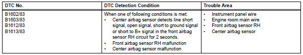
Dtc b1602/83, b1603/83, b1612/83 or b1613/83 is recorded when a malfunction is detected in the front airbag sensor rh circuit.
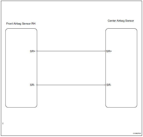
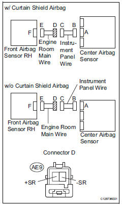
Wiring diagram
Inspection procedure
- Check connection of connector
- Turn the ignition switch off.
- Disconnect the cable from the negative (-) battery terminal, and wait for at least 90 seconds.
- Check that the connectors are properly connected to the center airbag sensor and the front airbag sensor rh.
Ok: the connectors are connected.

- Check front airbag sensor rh circuit (open)
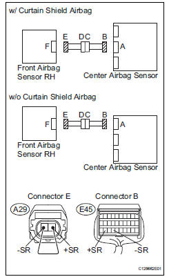
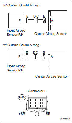
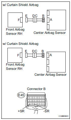
- Disconnect the connectors from the center airbag sensor and the front airbag sensor rh.
- Using a service wire, connect a29-2 (+sr) and a29-1 (- sr) of connector e.
Notice:
Do not forcibly insert a service wire into the terminals of the connector when connecting.
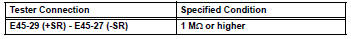
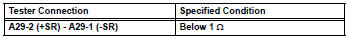
- Measure the resistance of the wire harness side connector.
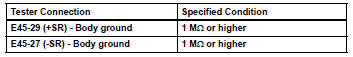
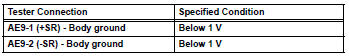
Standard resistance
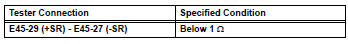

- Check front airbag sensor rh circuit (short)
- Disconnect the service wire from connector e.
- Measure the resistance of the wire harness side connector.
Standard resistance

- Check front airbag sensor rh circuit (to b+)
- Connect the cable to the negative (-) battery terminal, and wait for at least 2 seconds.
- Turn the ignition switch on.
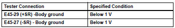
- Measure the voltage of the wire harness side connector.
Standard voltage

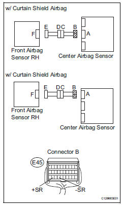
- Check front airbag sensor rh circuit (to ground)
- Turn the ignition switch off.
- Disconnect the cable from the negative (-) battery terminal, and wait for at least 90 seconds.
- Measure the resistance of the wire harness side connector.
Standard resistance


- Check front airbag sensor rh
- Connect the connectors to the center airbag sensor .
- Interchange the front airbag sensor rh and lh, and connect the connectors to them.
- Connect the cable to the negative (-) battery terminal, and wait for at least 2 seconds.
- Turn the ignition switch on, and wait for at least 60 seconds.
- Clear the dtcs (see page rs-49).
- Turn the ignition switch off.
- Turn the ignition switch on, and wait for at least 60 seconds.
- Check the dtcs (see page rs-49).
Result 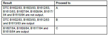
Hint:
Dtcs other than dtc b1602/83, b1603/83, b1612/83, b1613/83, b1607/84, b1608/84, b1617/84 and b1618/ 84 may be output at this time, but they are not related to this check.

Use simulation method to check
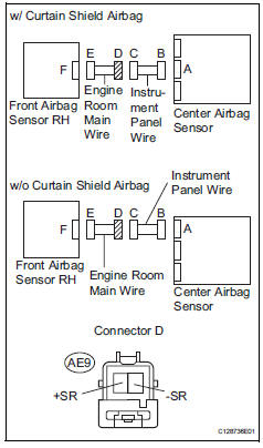
- Check engine room main wire (open)
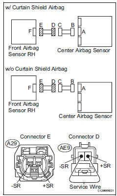
- Disconnect the service wire from connector e.
- Disconnect the engine room main wire connector from the instrument panel wire.
- Using a service wire, connect ae9-2 (+sr) and ae9-1 (- sr) of connector d.
Notice:
Do not forcibly insert a service wire into the terminals of the connector when connecting.
- Measure the resistance of the wire harness side connector.
Standard resistance

Repair or replace instrument panel wire
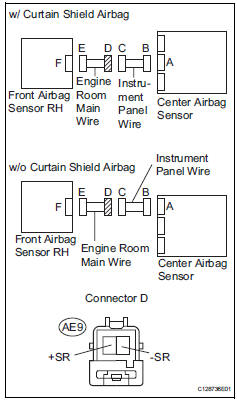
- Check engine room main wire (short)
- Disconnect the engine room main wire connector from the instrument panel wire.
- Disconnect the service wire from connector e.
- Measure the resistance of the wire harness side connector.
Standard resistance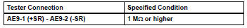

Repair or replace instrument panel wire
- Check engine room main wire (to b+)
- Turn the ignition switch off.
- Disconnect the cable from the negative (-) battery terminal, and wait for at least 90 seconds.
- Disconnect the engine room main wire connector from the instrument panel wire.
- Connect the cable to the negative (-) battery terminal, and wait for at least 2 seconds.
- Turn the ignition switch on.
- Measure the voltage of the wire harness side connector.
Standard voltage

Repair or replace instrument panel wire
- Check engine room main wire (to ground)
- Disconnect the engine room main wire connector from the instrument panel wire.
- Measure the resistance of the wire harness side connector.
Standard resistance

Repair or replace instrument panel wire
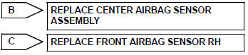
 Center airbag sensor assembly malfunction
Description
The center airbag sensor consists of the airbag sensor, the safing sensor,
the drive circuit, the diagnosis
circuit and the ignition control.
If the center airbag sensor receive ...
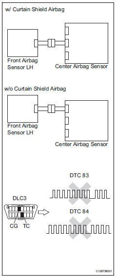
 Lost communication with front satellite sensor bus lh
Description
The front airbag sensor lh consists of the diagnostic circuit and the frontal
deceleration sensor.
If the center airbag sensor receives signals from the frontal deceleration
se ...
Other materials:
Removal (2006/01- )
Disconnect cable from negative battery
terminal
Caution:
Wait at least 90 seconds after disconnecting the
cable from the negative (-) battery terminal to
prevent airbag and seat belt pretensioner activation.
Remove air cleaner case sub-assembly (for
2az-fe)
Remove the air clea ...
Engine control system malfunction
Description
If a malfunction in the engine control system is detected, the operations of
vsc and trc are prohibited
by the fail-safe function. When the signals from the engine are input normally,
the fail-safe is canceled and
the dtc is not stored.
Inspection procedure
Check harn ...
Problem symptoms table
Hint:
Use the table below to help determine the cause of the
problem symptom. The potential causes of the symptoms
are listed in order of probability in the "suspected area"
column of the table. Check each symptom by checking the
suspected areas in the order they are listed. Re ...
