Toyota RAV4 (XA40) 2013-2018 Service Manual: Low battery positive voltage
![]()
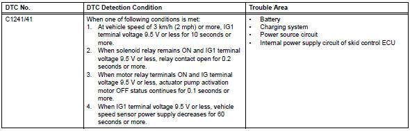
Description
When there is an abnormality in the power supply circuit of the brake actuator (skid control ecu), the skid control ecu sets a dtc and the operation is prohibited by the fail-safe function. This dtc is set when the voltage supplied to terminal ig1 is outside the dtc detection threshold, due to abnormalities of the battery, power source circuits or charging circuits such as the alternator circuit.
The fail-safe function is canceled when the voltage to terminal ig1 returns to normal.
Wiring diagram
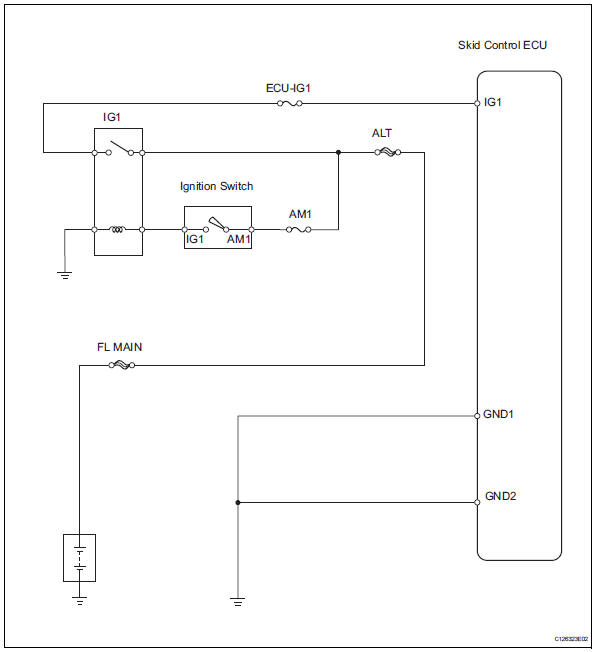
Inspection procedure
- Inspect fuse (ecu-ig1)
- Remove the ecu-ig1 fuse from the instrument panel junction block.
- Measure the resistance of the fuse.
Standard resistance:
below 1 


- Inspect battery
- Check the battery voltage.
Standard voltage: 11 to 14 v

- Check wire harness (skid control ecu - battery)
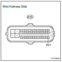
- Disconnect the a19 ecu connector.
- Measure the voltage of the wire harness side connector.
Standard voltage 

- Check wire harness (skid control ecu - body ground)
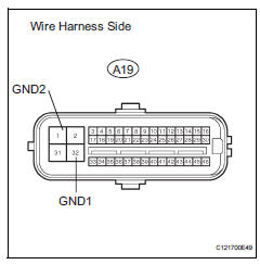
- Disconnect the a19 ecu connector.
- Measure the resistance of the wire harness side connector.
Standard resistance 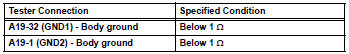

- Reconfirm dtc
- Clear the dtc (see page bc-47).
- Drive the vehicle at 3 km/h (2 mph) or more for several seconds.
- Check if the same dtc is output (see page bc-47).
Result 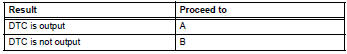

Replace abs and traction actuator assembly
 Stuck in deceleration sensor
Description
The skid control ecu receives signals from the yaw rate and deceleration
sensor via the can
communication system.
The yaw rate sensor has a built-in deceleration sensor and dete ...
 Master cylinder pressure sensor malfunction
Description
The master cylinder pressure sensor is connected to the skid control ecu in
the abs and traction
actuator.
Dtc c1281/81 can be detected when the master cylinder pressure sensor ...
Other materials:
Rear brake
Components
Removal
Hint:
Use the same procedures for the lh side and rh side.
The procedures listed below are for the lh side.
Remove rear wheel
Drain brake fluid
Notice:
Wash off brake fluid immediately if it comes in
contact with any painted surface.
Disconnect rea ...
Brake pedal load sensing switch
Description
The brake pedal load sensing switch is turned on when the brake pedal is
depressed with force exceeding
a predetermined level.
The skid control ecu detects if the brake pedal is depressed or not via this
circuit.
Wiring diagram
Inspection procedure
Notice:
When repla ...
Spiral cable
Components
Removal
Caution:
Be sure to read the precautionary notices concerning the
srs airbag system before servicing it (see page rs-1).
Disconnect cable from negative battery
terminal
Caution:
Wait at least 90 seconds after disconnecting the
cable from the negative (-) battery ...
