Toyota RAV4 Service Manual: Occupant classification sensor power supply circuit malfunction
Description
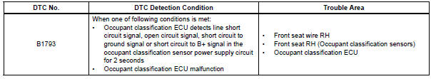
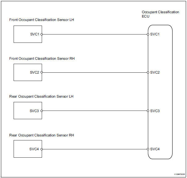
The occupant classification sensor power supply circuit consists of the occupant classification ecu and the occupant classification sensors.
Dtc b1793 is recorded when a malfunction is detected in the occupant classification sensor power supply circuit.
Wiring diagram
Inspection procedure
Hint:
- If troubleshooting (wire harness inspection) is difficult to perform, remove the front passenger seat installation bolts to see the undersurface of the seat cushion.
- In the above case, hold the seat so that it does not tip over. Holding the seat for a long period of time may cause a problem, such as seat rail deformation. Hold the seat up only for as long as necessary.
- Check for dtc
- Turn the ignition switch on.
- Clear the dtcs (see page rs-249).
Hint:
First clear dtcs stored in the occupant classification ecu and then in the center airbag sensor.
- Turn the ignition switch off.
- Turn the ignition switch on.
- Check the dtcs (see page rs-249).
Ok: dtc b1793 is not output.
Hint:
Dtcs other than dtc b1793 may be output at this time, but they are not related to this check.

- Check connection of connector
- Turn the ignition switch off.
- Disconnect the cable from the negative (-) battery terminal, and wait for at least 90 seconds.
- Check that the connectors are properly connected to the occupant classification ecu and the occupant classification sensors.
Ok: the connectors are properly connected.


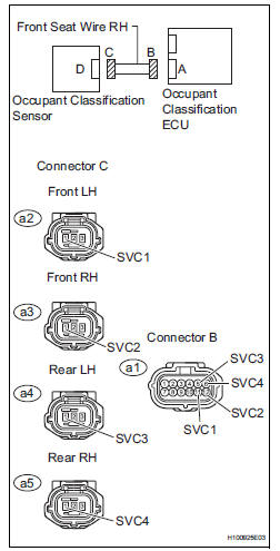
- Check front seat wire rh (to b+)
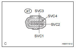
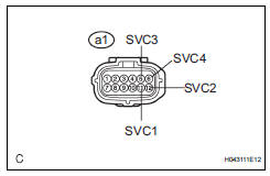
- Disconnect the connectors from the occupant classification ecu and the 4 occupant classification sensors.
- Connect the negative (-) terminal cable to the battery, and wait for at least 2 seconds.
- Turn the ignition switch on.
- Measure the voltage of the wire harness side connector.
Standard voltage 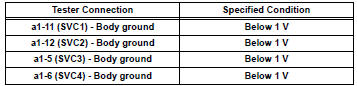

- Check front seat wire rh (to ground)
- Turn the ignition switch off.
- Disconnect the cable from the negative (-) battery terminal, and wait for at least 90 seconds.
- Measure the resistance of the wire harness side connector.
Standard resistance 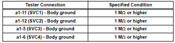

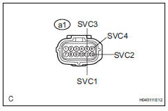
- Check front seat wire rh (for open)
- Measure the resistance of the wire harness side connectors.
Standard resistance 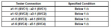

- Check front seat wire rh (for short)
- Measure the resistance of the wire harness side connector.
Standard resistance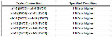

- Check for dtc
- Connect the connectors to the occupant classification ecu and the 4 occupant classification sensors.
- Connect the cable to the negative (-) battery terminal, and wait for at least 2 seconds.
- Turn the ignition switch on.
- Clear the dtcs (see page rs-249).
Hint:
First clear dtcs stored in the occupant classification ecu and then in the center airbag sensor.
- Turn the ignition switch off.
- Turn the ignition switch on.
- Check the dtcs (see page rs-249).
Ok: dtc b1793 is not output.
Hint:
Dtcs other than dtc b1793 may be output at this time, but they are not related to this check.

- Replace occupant classification ecu
- Turn the ignition switch off.
- Disconnect the cable from the negative (-) battery terminal, and wait for at least 90 seconds.
- Replace the occupant classification ecu (see page rs- 392).
Hint:
Perform the inspection using parts from a normal vehicle if possible.

- Perform zero point calibration
- Connect the cable to the negative (-) battery terminal, and wait for at least 2 seconds.
- Connect the intelligent tester to the dlc3.
- Turn the ignition switch on.
- Using the intelligent tester, perform the zero point calibration (see page rs-241).
Ok: completed is displayed.

- Perform sensitivity check
- Using the intelligent tester, perform the sensitivity check (see page rs-241).
Standard value: 27 to 33 kg (59.52 To 72.75 Lb)

- Check for dtc
- Connect the negative (-) terminal cable to the battery, and wait for at least 2 seconds.
- Turn the ignition switch on.
- Clear the dtcs (see page rs-249).
Hint:
First clear dtcs stored in the occupant classification ecu and then in the center airbag sensor.
- Turn the ignition switch off.
- Turn the ignition switch on.
- Check the dtcs (see page rs-249).
Ok: dtc b1793 is not output.
Hint:
Dtcs other than dtc b1793 may be output at this time, but they are related to this check.

- Replace front seat assembly rh
- Turn the ignition switch off.
- Disconnect the cable from the negative (-) battery terminal, and wait for at least 90 seconds
- Replace the front seat rh (see page se-8).

- Perform zero point calibration
- Connect the cable to the negative (-) battery terminal, and wait for at least 2 seconds.
- Connect the intelligent tester to the dlc3.
- Turn the ignition switch on.
- Using the intelligent tester, perform the zero point calibration (see page rs-241).
Ok: completed is displayed.

- Perform sensitivity check
- Using the intelligent tester, perform the sensitivity check (see page rs-241).
Standard value: 27 to 33 kg (59.52 To 72.75 Lb)

End
 Center airbag sensor assembly communication circuit malfunction
Description
The center airbag sensor communication circuit consists of the occupant
classification ecu and the
center airbag sensor.
Dtc b1790 is recorded when a malfunction is detected in ...
 Open in occupant classification ecu battery positive line
Description
Dtc b1794 is set when a malfunction is detected in the occupant
classification ecu battery positive line.
Wiring diagram
Inspection procedure
Check for dtc
Turn ...
Other materials:
Evap system
Related dtcs
If any evap system dtcs are set, the malfunctioning area can be determined
using the table below.
Notice:
If the reference pressure difference between the first and second checks
is greater than the
specification, all the dtcs relating to the reference pressure (p043e, p ...
Disassembly
Remove park/neutral position switch assembly
Remove the nut, washer and control shaft lever.
Using a screwdriver, pry off the lock plate.
Remove the nut and lock plate.
Remove the 2 bolts and pull out the switch.
Remove breather plug hose
Remove oil coo ...
Purpose of readiness tests
The on-board diagnostic (obd ii) system is designed to
monitor the performance of emission related components,
and indicate any detected abnormalities with dtc
(diagnostic trouble codes). Since various components
need to be monitored during different driving conditions,
the obd ii syste ...
