
Toyota RAV4 (XA40) 2013-2018 Service Manual: Parking brake lever
Components
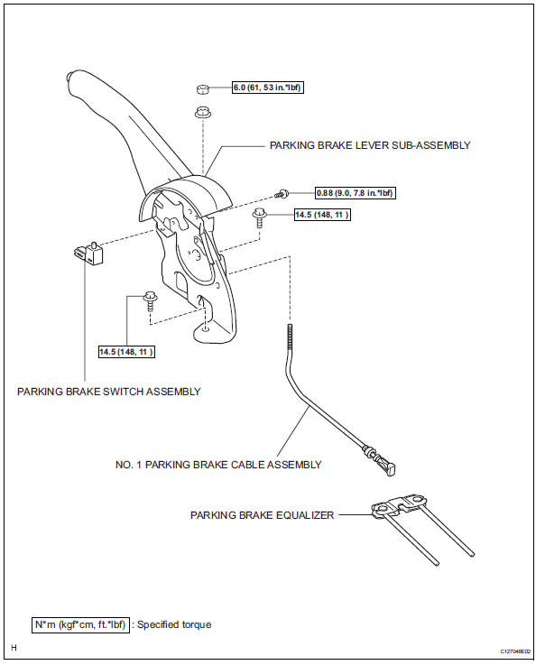
On-vehicle inspection
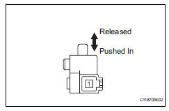
- Check parking brake switch assembly
- Remove the rear console box (see page ip-16).
Hint:
Refer to the procedures from the removal of the no.
1 Console upper panel garnish up until the removal of the rear console box sub-assembly.
- Disconnect the parking brake switch connector.
- Measure the resistance of the switch.
Standard resistance
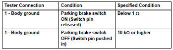
If the result is not as specified, replace the switch assembly.
Removal
- Disconnect cable from negative battery terminal
Caution:
Wait at least 90 seconds after disconnecting the cable from the negative (-) battery terminal to prevent airbag and seat belt pretensioner activation.
- Remove rear console box sub-assembly
- Remove the rear console box (see page ip-16).
Hint:
Refer to the procedures from the removal of the no.
1 Console upper panel garnish up until the removal of the rear console box sub-assembly.
- Remove parking brake lever sub-assembly
- Disconnect the parking brake switch connector.
- Remove the lock nut and wire adjusting nut.
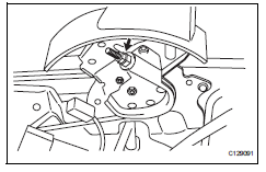
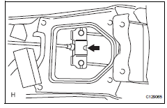
- Disconnect the no. 1 Parking brake cable from the parking brake equalizer.
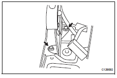
- Remove the 2 bolts and parking brake lever (with the no. 1 Parking brake cable).
- Remove no. 1 Parking brake cable assembly
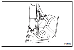
- Disconnect the cable from the lever.
- Remove parking brake switch assembly
- Remove the screw and switch from the lever.
Installation
- Install parking brake switch assembly
- Install the parking brake switch with the screw.
Torque: 0.88 N*m (9.0 Kgf*cm, 7.8 In.*Lbf)
- Install no. 1 Parking brake cable assembly
- Connect the cable to the lever.
- Install parking brake lever sub-assembly
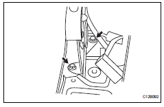
- Install the parking brake lever (with the no. 1
Parking brake cable) with the 2 bolts.
Torque: 14.5 N*m (148 kgf*cm, 11 ft.*Lbf)
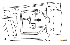
- Connect the no. 1 Parking brake cable to the parking brake equalizer.
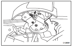
- Temporarily install the wire adjusting nut and lock nut.
- Connect the parking brake switch connector.
- Check parking brake lever travel (see page pb-1)
- Adjust parking brake lever travel (see page pb-2)
- Install rear console box sub-assembly
- Install the rear console box (see page ip-23).
Hint:
Refer to the procedures from the installation of the rear console box sub-assembly up until the installation of the no. 1 Console upper panel garnish.
- Connect cable to negative battery terminal
 Parking brake system
Problem symptoms table
Hint:
Use the table below to help determine the cause of the
problem symptom. The potential causes of the symptoms are
listed in order of probability in the "suspected ...
 Parking brake cable
Components
Removal
Remove rear console box sub-assembly
Remove the rear console box (see page ip-16).
Hint:
Refer to the procedures from the removal of the no.
1 Console upper p ...
Other materials:
Rear occupant classification sensor rh collision detection
Description
Dtc b1788 is output when the occupant classification ecu receives a collision
detection signal sent by
the rear occupant classification sensor rh when an accident occurs.
Dtc b1788 is also output when the front seat rh is subjected to a strong impact,
even if an actual
acci ...
Driving position memory
Your preferred driving position (the position of the driver’s seat) can
be recorded and recalled by pressing a button.
Two different driving positions can be recorded into memory.
Recording procedure
Check that the shift lever is in p.
Turn the engine switch to the “on� position (ve ...
Steering angle sensor circuit malfunction
Description
The steering sensor signal is sent to the skid control ecu via the can
communication system. When
there is a malfunction in the can communication system, it is detected by the
steering sensor zero point
malfunction diagnostic function.
Wiring diagram
Inspection proce ...
