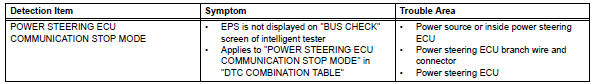
Toyota RAV4 (XA40) 2013-2018 Service Manual: Power steering ecu communication stop mode
Description
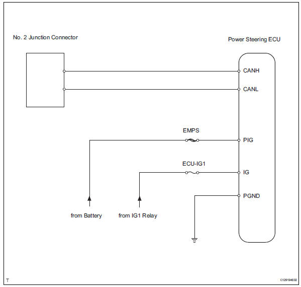
Wiring diagram
Inspection procedure
Notice:
- Turn the ignition switch off before measuring the resistances of the main wire and the branch wire.
- After the ignition switch is turned off, check that the key reminder warning system and light reminder warning system are not in operation.
- Before measuring the resistance, leave the vehicle for at least 1 minute and do not operate the ignition switch, any switches or doors. If doors need to be opened in order to check connectors, open the doors and leave them open.
Hint:
Operating the ignition switch, any switches or any doors triggers related ecu and sensor communication with the can, which causes resistance variation.
- Check can bus line for disconnection (power steering ecu main wire)
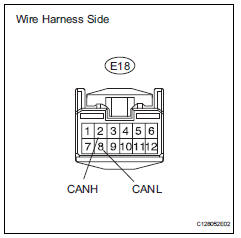
- Disconnect the e18 power steering ecu connector.
- Measure the resistance of the wire harness side connector.
Standard resistance 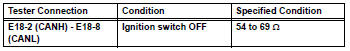

- Check wire harness (power steering ecu - battery and body ground)
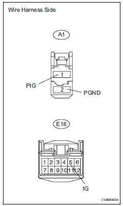
- Disconnect the a1 and e18 power steering ecu connectors.
- Measure the resistance of the wire harness side connector.
Standard resistance 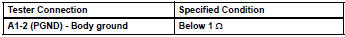
- Measure the voltage of the wire harness side connectors.
Standard voltage 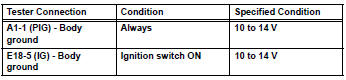

Replace power steering ecu
 Air conditioning amplifier communication stop mode
Description
Wiring diagram
Inspection procedure
Notice:
Turn the ignition switch off before measuring the resistances
of the main wire and the branch
wire.
After the ignition ...
 Steering angle sensor communication stop mode
Description
Wiring diagram
Inspection procedure
Notice:
Turn the ignition switch off before measuring the resistances of the
main wire and the branch
wire.
After the ignition swi ...
Other materials:
RCTA function
â– Operation of the RCTA
function
The RCTA function uses rear
side radar sensors to detect
vehicles approaching from the right or left at the rear of the
vehicle and alerts the driver of
the presence of such vehicles
by flashing the outside rear view
mirror indicators and sounding a
buzzer.
Appr ...
Light bulbs
You may replace the following bulbs by yourself. The difficulty
level of replacement varies depending on the bulb. If necessary
bulb replacement seems difficult to perform, contact your
toyota dealer.
For more information about replacing other light bulbs, contact
your toyota dealer.
Prepari ...
Brake warning light does not come on
Wiring diagram
Refer to the brake warning light circuit (see page bc-145).
Inspection procedure
Check can communication system
Check if the can communication system dtc is output
(see page ca-34).
Result
Perform active test by intelligent tester (brake warning light)
...
