Toyota RAV4 Service Manual: Pressure control solenoid "A " performance (shift solenoid valve sl1)
Description
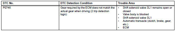
The ecm uses signals from the vehicle speed sensor to detect the actual gear position (1st, 2nd, 3rd or o/d gear).
Then the ecm compares the actual gear with the shift schedule in the ecm memory to detect mechanical problems of the shift solenoid valves, valve body or automatic transaxle (clutch, brake, gear, etc.).
Monitor description
The ecm commands gear shifts by turning the shift solenoid valves on/off. According to the input shaft revolution, intermediate (counter) shaft revolution and output shaft revolution, the ecm detects the actual gear position (1st, 2nd, 3rd or o/d gear position). When the gear position commanded by the ecm and the actual gear position are not the same, the ecm illuminates the mil.
Example: when either condition (a) or (b) is met, the ecm detects a malfunction.
- The ecm commands the 1st gear, but the actual gear is 2nd.
- The ecm commands the 2nd gear, but the actual gear is 1st.
Monitor strategy
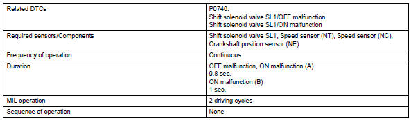
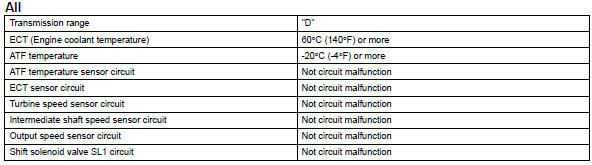
Typical enabling conditions
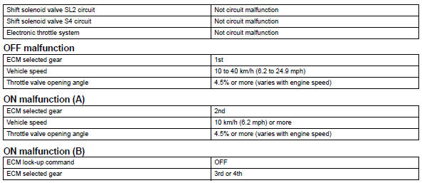
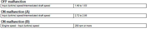
Typical malfunction thresholds
Either of the following conditions is met: off malfunction, or on malfunction (a) and (b) 2 detections are necessary per driving cycle: 1st detection: temporary flag on
2Nd detection: pending fault code on
Inspection procedure
Hint:
Performing the intelligent tester's active test allows relay, vsv, actuator and other items to be operated without removing any parts. Performing the active test early in troubleshooting is one way to save time.
The data list can be displayed during the active test.
- Warm up the engine.
- Turn the ignition switch off.
- Connect the intelligent tester to the can vim. Then connect the can vim to the dlc3.
- Turn the ignition switch on and turn the tester on.
- Enter the following menus: diagnosis / enhanced obd ii / active test.
- Follow the instructions on the tester and read the active test.
Hint:
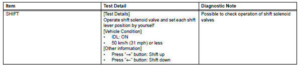
While driving, the shift position can be forcibly changed with the tester. Comparing the shift position commanded by the active test with the actual shift position enables you to confirm the problem (see page ax-31).
Hint:
- This test can be conducted when the vehicle speed is 50 km/h (31 mph) or more.
- This shift position commanded by the ecm is shown in the data list/shift display on the tester.
- Check other dtc output (in addition to dtc p0746)
- Connect the intelligent tester to the can vim. Then connect the can vim to the dlc3.
- Turn the ignition switch on and turn the tester on.
- Enter the following menus: diagnosis / enhanced obd ii / dtc info / current codes.
- Read the dtcs using the tester.
Result 
Hint:
If any other codes besides p0746 are output, perform the troubleshooting for those dtcs first.


- Inspect shift solenoid valve sl1
- Remove the shift solenoid valve sl1.
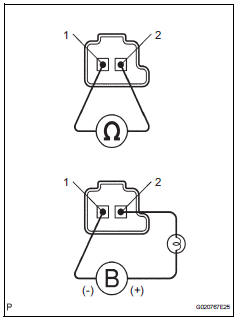
- Measure the resistance of the solenoid valve.
Standard resistance: 5.0 To 5.6 Ùat 20°c (68°f)
- Connect the battery's positive (+) lead with a 21 w bulb to terminal 2 and the negative (-) lead to terminal 1 of the solenoid valve connector. Then check that the valve moves and makes an operating noise.
Ok: valve moves and makes operating noise.


- Inspect transmission valve body assembly
- Check the transmission valve body assembly.
Ok: there are no foreign objects on each valve.


- Inspect torque converter clutch assembly
- Check the torque converter clutch assembly (see page ax-153).
Ok: the torque converter clutch operates normally.


Repair or replace automatic transaxle assembly
 Torque converter clutch solenoid performance (shift solenoid valve dsl)
Description
The ecm uses the signals from the throttle position sensor, air-flow meter,
turbine (input) speed sensor,
intermediate (counter) shaft speed sensor and crankshaft position sensor t ...
 Pressure control solenoid "A" electrical (shift solenoid valve sl1)
Description
Shifting from 1st to o/d is performed in combination with the on and off
operation of the shift solenoid
valves sl1 and sl2, which are controlled by the ecm. If an open or short circu ...
Other materials:
Front power seat lumbar switch
Inspection
Inspect front power seat lumbar switch lh
Measure the resistance between the terminals when
the switch is operated.
Standard resistance
If the result is not as specified, replace the switch. ...
Position initialization incomplete
Description
This dtc is output when the sliding roof drive gear (sliding roof ecu) has
not been initialized.
Wiring diagram
Refer to dtc b2341 (see page rf-11).
Inspection procedure
Initialize sliding roof drive gear sub-assembly (sliding roof ecu)
Check that the sliding roof ...
Diagnosis system
Check dlc3
The ecm uses iso 15765-4 for communication. The
terminal arrangement of the dlc3 complies with sae
j1962 and matches the iso 15765-4 format.
If the result is not as specified, the dlc3 may have a
malfunction. Repair or replace the harness and
connector.
Hint:
Conn ...
