Toyota RAV4 (XA40) 2013-2018 Service Manual: Short in front driver side pretensioner squib circuit
Description
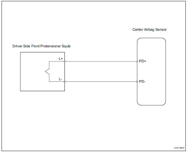
The driver side front pretensioner squib circuit consists of the center airbag sensor and the front seat outer belt lh.
This circuit instructs the srs to deploy when the deployment conditions are met.
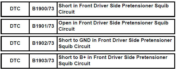
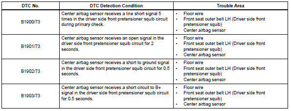
These dtcs are recorded when a malfunction is detected in the front pretensioner squib circuit.
Wiring diagram
Inspection procedure
Hint:
- Perform the simulation method by selecting the "check mode" (signal check) with the intelligent tester (see page rs-52).
- After selecting the "check mode" (signal check), perform the simulation method by wiggling each connector of the airbag system or driving the vehicle on a city or rough road (see page rs-52).
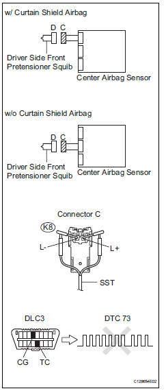
- Check front seat outer belt assembly lh (driver side front pretensioner squib)
- Turn the ignition switch off.
- Disconnect the cable from the negative (-) battery terminal, and wait for at least 90 seconds.
- Disconnect the connectors from the front seat outer belt lh.
- Connect the white wire side of sst to connector c.
Caution:
Never connect a tester to the front seat outer belt lh (driver side front pretensioner squib) for measurement, as this may lead to a serious injury due to airbag deployment.
Notice:
- Do not forcibly insert sst into the terminals of the connector when connecting.
- Insert sst straight into the terminals of the connector.
Sst 09843-18060
- Connect the cable to the negative (-) battery terminal, and wait for at least 2 seconds.
- Turn the ignition switch on, and wait for at least 60 seconds.
- Clear the dtcs (see page rs-49).
- Turn the ignition switch off.
- Turn the ignition switch on, and wait for at least 60 seconds.
- Check the dtcs (see page rs-49).
Ok: dtc b1900, b1901, b1902, b1903 or 73 is not output.
Hint:
Dtcs other than dtc b1900, b1901, b1902, b1903 or 73 may be output at this time, but they are not related to this check.

- Check connector
- Turn the ignition switch off.
- Disconnect the cable from the negative (-) battery terminal, and wait for at least 90 seconds.
- Disconnect sst from connector c.
- Check that the floor wire connector (on the driver side front seat outer belt) is not damaged.
Ok: the lock button is not disengaged, or the claw of the lock is not deformed or damaged.

- Check floor wire (driver side front pretensioner squib circuit)
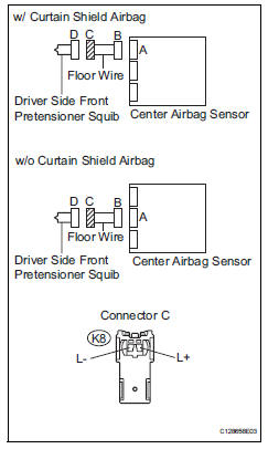
- Disconnect the connector from the center airbag sensor.
- Connect the cable to the negative (-) battery terminal, and wait for at least 2 seconds.
- Turn the ignition switch on.
- Measure the voltage of the wire harness side connector.
Standard voltage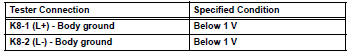
- Release the activation prevention mechanism built into connector b (see page rs-37).
- Measure the resistance of the wire harness side connector.
Standard resistance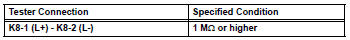

Replace center airbag sensor assembly
 Short in front passenger side curtain shield squib circuit
Description
The front passenger side curtain shield squib circuit consists of the center
airbag sensor and the curtain
shield airbag rh.
The circuit instructs the srs to deploy when the dep ...
 Short in front passenger side pretensioner squib circuit
Description
The front passenger side front pretensioner squib circuit consists of the
center airbag sensor and the front
seat outer belt rh.
This circuit instructs the srs to deploy whe ...
Other materials:
Compressor solenoid circuit (2005/11-2006/01)
Description
In this circuit, the compressor receives a refrigerant compression demand
signal from the air conditioning
amplifier. Based on this signal, the compressor changes the degree of
refrigerant compression.
Wiring diagram
Inspection procedure
Read value of intelligent ...
Fuel pressure regulator
Components
Removal
Remove fuel tank assembly
Remove the fuel tank (see page fu-39).
Remove fuel tank main tube sub-assembly
Remove the joint clip and fuel tank main tube.
Caution:
Before removing the tube joint clip, check for
foreign matter around the cli ...
Wireless charger (if
equipped)
A portable device can be
charged by just placing Qi standard
wireless charge compatible
portable devices according to
the Wireless Power Consortium,
such as smartphones and
mobile batteries, etc., on the
charge area.
This function cannot be used
with portable devices that are
larger than the chargi ...
