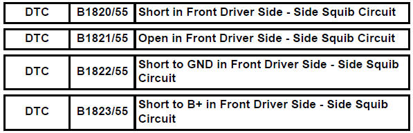
Toyota RAV4 (XA40) 2013-2018 Service Manual: Short in front driver side - side squib circuit
Description
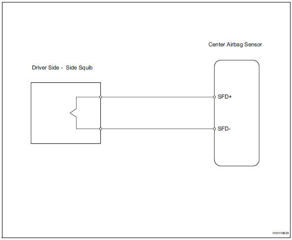
The driver side - side squib circuit consists of the center airbag sensor and the front seat side airbag lh.
This circuit instructs the srs to deploy when the deployment conditions are met.
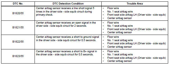
These dtcs are recorded when a malfunction is detected in the driver side - side squib circuit.
Wiring diagram
Inspection procedure
Hint:
- Perform the simulation method by selecting the "check mode" (signal check) with the intelligent tester (see page rs-52).
- After selecting the "check mode" (signal check), perform the simulation method by wiggling each connector of the airbag system or driving the vehicle on a city or rough road (see page rs-52).
- Check front seat side airbag assembly lh (driver side - side squib)
- Turn the ignition switch off.
- Disconnect the cable from the negative (-) battery terminal, and wait for at least 90 seconds.
- Disconnect the connector from the front seat side airbag lh.
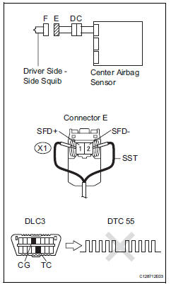
- Connect the black wire side of sst to connector e.
Caution:
Never connect a tester to the front seat side airbag lh (driver side - side squib) for measurement, as this may lead to a serious injury due to airbag deployment.
Notice:
- Do not forcibly insert sst into the terminals of the connector when connecting.
- Insert sst straight into the terminals of the connector
Sst 09843-18060
- Connect the cable to the negative (-) battery terminal, and wait for at least 2 seconds.
- Turn the ignition switch on, and wait for at least 60 seconds.
- Clear the dtcs (see page rs-49).
- Turn the ignition switch off
- Turn the ignition switch on, and wait for at least 60 seconds.
- Check the dtcs (see page rs-49).
Ok: dtc b1820, b1821, b1822, b1823 or 55 is not output.
Hint:
Dtcs other than dtc b1820, b1821, b1822, b1823 or 55 may be output at this time, but they are not related to this check.


- Check connector
- Turn the ignition switch off.
- Disconnect the cable from the negative (-) battery terminal, and wait for at least 90 seconds.
- Disconnect sst from the no. 1 Seat airbag wire.
- Check that the floor wire connectors (on the driver side - side squib) are not damaged.
Ok: lock button is not disengaged, and claw of lock is not deformed or damaged.

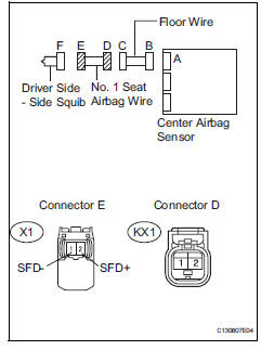
- Check floor wire (driver side - side squib circuit)
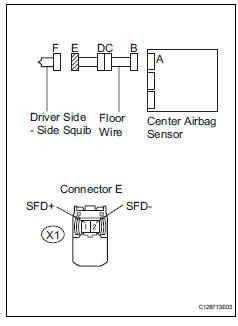
- Disconnect the connector from the center airbag sensor.
- Connect the cable to the negative (-) battery terminal, and wait for at least 2 seconds.
- Turn the ignition switch on.
- Measure the voltage of the wire harness side connector.
Standard voltage 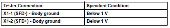
- Turn the ignition switch off.
- Disconnect the cable from the negative (-) battery terminal, and wait for at least 90 seconds.
- Measure the resistance of the wire harness side connector.
Standard resistance 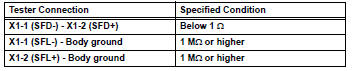
- Release the activation prevention mechanism built into connector b (see page rs-37).
- Measure the resistance of the wire harness side connector
Standard resistance 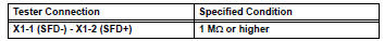

- Check no. 1 Seat airbag wire
- Disconnect the no. 1 Seat airbag wire connector from the floor wire.
- Connect the cable to the negative (-) battery terminal, and wait for at least 2 seconds.
- Turn the ignition switch on.
- Measure the voltage of the wire harness side connector.
Standard voltage 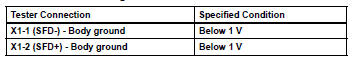
- Turn the ignition switch off.
- Disconnect the cable from the negative (-) battery terminal, and wait for at least 90 seconds.
- Measure the resistance of the wire harness side connector.
Standard resistance 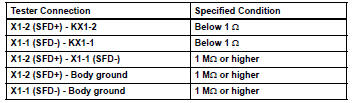

Repair or replace floor wire
 Short in front passenger side squib 2nd step circuit
Description
The front passenger side squib 2nd step circuit consists of the center airbag
sensor and the front
passenger airbag.
The circuit instructs the srs to deploy when the deployment ...
 Short in front passenger side - side squib circuit
Description
The front passenger side - side squib circuit consists of the center airbag
sensor and the front seat side
airbag rh.
The circuit instructs the srs to deploy when the deployment ...
Other materials:
Rear window wiper
and washer
Turning the end of the lever turns on the rear window wiper, and pushing
the lever away from you turns on the rear window wiper and
washer.
For the u.S.A.
Intermittent operation
Normal operation
Washer/wiper dual operation
For Canada
Intermittent operation
Normal oper ...
Winter driving tips
Carry out the necessary
preparations and inspections
before driving the
vehicle in winter. Always
drive the vehicle in a manner
appropriate to the prevailing
weather conditions.
Pre-winter preparations
Use fluids that are appropriate
to the prevailing outside temperatures.
Engine oil
Engine c ...
Front occupant classification sensor rh collision detection
Description
Dtc b1786 is output when the occupant classification ecu receives a collision
detection signal sent by
the front occupant classification sensor rh when an accident occurs.
Dtc b1786 is also output when the front seat assembly rh is subjected to a
strong impact, even if an
a ...
