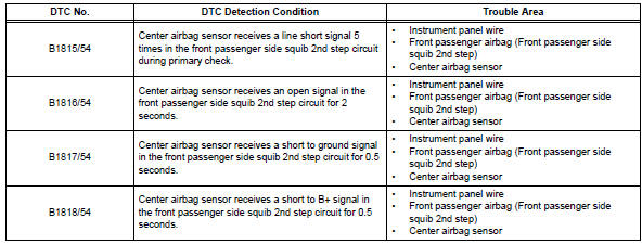
Toyota RAV4 (XA40) 2013-2018 Service Manual: Short in front passenger side squib 2nd step circuit
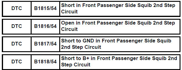
Description
The front passenger side squib 2nd step circuit consists of the center airbag sensor and the front passenger airbag.
The circuit instructs the srs to deploy when the deployment conditions are met.
These dtcs are recorded when a malfunction is detected in the front passenger side squib 2nd step circuit.
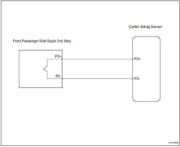
Wiring diagram
Inspection procedure
Hint:
- Perform the simulation method by selecting the "check mode" (signal check) with the intelligent tester (see page rs-52).
- After selecting the "check mode" (signal check), perform the simulation method by wiggling each connector of the airbag system or driving the vehicle on a city or rough road (see page rs-52).
- Check front passenger airbag assembly (front passenger side squib 2nd step)
- Turn the ignition switch off.
- Disconnect the cable from the negative (-) battery terminal, and wait for at least 90 seconds.
- Disconnect the connector from the front passenger airbag.
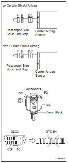
- Connect the white wire side of sst to the instrument panel wire connector e.
Caution:
never connect a tester to the front passenger airbag (front passenger side squib 2nd step) for measurement, as this may lead to a serious injury due to airbag deployment.
Notice:
- Do not forcibly insert sst into the terminals of the connector when connecting.
- Insert sst straight into the terminals of the connector.
Sst 09843-18060
- Connect the cable to the negative (-) battery terminal, and wait for at least 2 seconds.
- Turn the ignition switch on, and wait for at least 60 seconds.
- Clear the dtcs (see page rs-49).
- Turn the ignition switch off
- Turn the ignition switch on, and wait for at least 60 seconds.
- Check the dtcs (see page rs-49).
Ok: dtc b1815, b1816, b1817, b1818 or 54 is not output.
Hint:
Dtcs other than dtc b1815, b1816, b1817, b1818 and 54 may be output at this time, but they are not related to this check.

- Check connector
- Turn the ignition switch off.
- Disconnect the cable from the negative (-) battery terminal, and wait for at least 90 seconds.
- Disconnect sst (resistance 2.1 Ù) from the instrument panel wire.
- Check that the instrument panel wire connectors (on the front passenger side airbag) are not damaged.
Ok: lock button is not disengaged, and claw of lock is not deformed or damaged.

- Check instrument panel wire
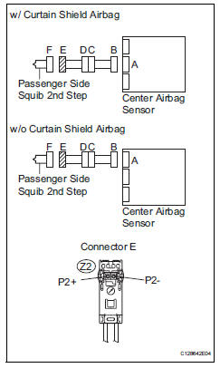
- Disconnect the connector from the center airbag sensor.
- Connect the cable to the negative (-) battery terminal, and wait for at least 2 seconds.
- Turn the ignition switch on.
- Measure the voltage of the wire harness side connector.
Standard voltage 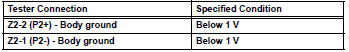
- Turn the ignition switch off
- Disconnect the cable from the negative (-) battery terminal, and wait for at least 90 seconds.
- Measure the resistance of the wire harness side connector.
Standard resistance 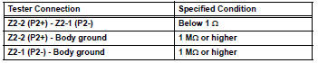
- Release the activation prevention mechanism built into connector b (see page rs-37).
- Measure the resistance of the wire harness side connector.
Standard resistance 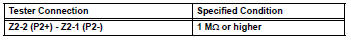

- Check no. 2 Instrument panel wire
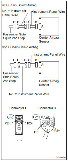
- Disconnect the no. 2 Instrument panel wire connector from the instrument panel wire.
- Connect the cable to the negative (-) battery terminal, and wait for at least 2 seconds.
- Turn the ignition switch on.
- Measure the voltage of the wire harness side connector.
Standard voltage 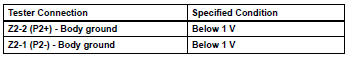
- Turn the ignition switch off.
- Disconnect the cable from the negative (-) battery terminal, and wait for at least 90 seconds.
- Measure the resistance of the wire harness side connector.
Standard resistance 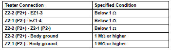

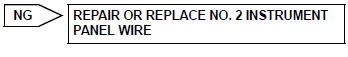
Repair or replace instrument panel wire
 Short in driver side squib 2nd step circuit
Description
The driver side squib 2nd step circuit consists of the center airbag sensor,
the spiral cable and the
steering pad.
The circuit instructs the srs to deploy when the deployment c ...
 Short in front driver side - side squib circuit
Description
The driver side - side squib circuit consists of the center airbag sensor and
the front seat side airbag lh.
This circuit instructs the srs to deploy when the deployment conditio ...
Other materials:
Maintenance data (fuel, oil
level, etc.)
Dimensions and weights
*1:Unladen vehicle
*2:Vehicles without 235/55R19 tires
*3:Vehicles with 235/55R19 tires
*4:Vehicles without towing package
*5:Vehicles with towing package
Seating capacity
Vehicle identification
â– Vehicle identification number
The vehicle identification number
(VIN) is the ...
Horn system
Parts location
System diagram
Problem symptoms table
Hint:
Use the table below to help determine the cause of the
problem symptom. The potential causes of the symptoms are
listed in order of probability in the "suspected area" column of
the table. Check each symptom by c ...
Gauges and meters
The units used on the speedometer may differ depending on the target
region.
Tachometer
Displays the engine speed in revolutions per minute
Speedometer
Displays the vehicle speed
Fuel gauge
Displays the quantity of fuel remaining in the tank
Shift position and shift ran ...
