Toyota RAV4 Service Manual: Solar sensor circuit (passenger side)
![]()
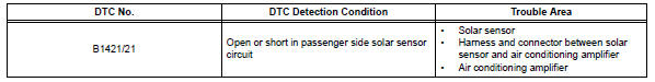
Description
The solar sensor, which is installed on the upper side of the instrument panel, detects sunlight and controls the air conditioning auto mode. The output voltage from the solar sensor varies in accordance with the amount of sunlight. When the sunlight increases, the output voltage increases. As the sunlight decreases, the output voltage decreases.
The air conditioning amplifier detects changes in the output voltage from the solar sensor.
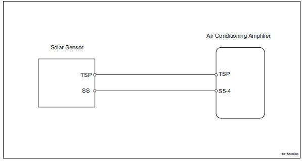
Wiring diagram
Inspection procedure
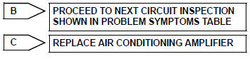
- Read value of intelligent tester (solar sens-p)
- Connect the intelligent tester (with can vim) to the dlc3.
- Turn the ignition switch on and turn the intelligent tester main switch on.
- Select the item below in the data list, and read the value displayed on the intelligent tester.
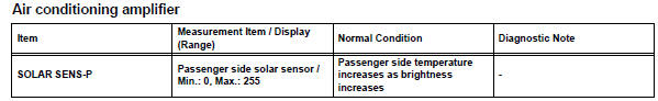
Ok: the display is as specified in the normal condition column.

- Inspect cooler (solar sensor) thermistor
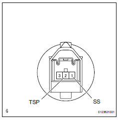
- Remove the solar sensor.
- Measure the resistance of the sensor.
- Connect the ohmmeter's positive (+) lead to terminal 1 and the negative (-) lead to terminal 2 of the solar sensor.
Standard resistance 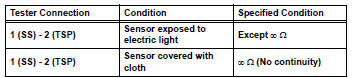
Notice:
The connection procedure for using a digital tester such as an electrical tester is shown above. When using an analog tester, connect the positive (+) lead to terminal 2 and the negative (-) lead to terminal 1 of the solar sensor.
Hint:
- As the inspection light is moved away from the sensor, the voltage decreases.
- Use an incandescent light for the inspection. Position it about 30 cm (11.8 In.) From the solar sensor.


- Check wire harness (solar sensor - air conditioning amplifier)
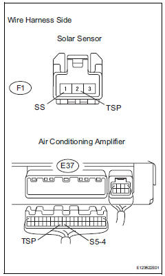
- Disconnect the f1 sensor connector.
- Disconnect the e37 amplifier connector.
- Measure the resistance of the wire harness side connectors.
Standard resistance 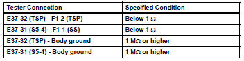

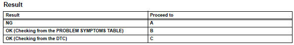
Replace air conditioning amplifier
 Evaporator temperature sensor circuit
Description
The no. 1 Cooler thermistor (evaporator temperature sensor) is installed on
the evaporator in the air
conditioning unit to detect the temperature of the cooled air that has passed ...
 Compressor lock sensor circuit
Description
This sensor sends 1 pulse per engine revolution to the air conditioning
amplifier. If the ratio of the
compressor speed divided by the engine speed is smaller than a predetermined ...
Other materials:
Front airbag sensor rh circuit malfunction
Description
The front airbag sensor rh consists of the diagnostic circuit, the frontal
deceleration sensor, etc.
If the center airbag sensor assembly receives signals from the frontal
deceleration sensor, it determines
whether or not the srs should be activated.
Dtc b1610/13 is recor ...
Horn relay
On-vehicle inspection
Remove engine room no. 1 Relay block cover
Inspect integration relay (unit a: horn relay)
Using a screwdriver, detach the 2 claws and
disconnect the integration relay from the engine
room junction block.
Hint:
Tape the screwdriver tip before use.
Mea ...
Air conditioning control panel does not operate
Description
This circuit consists of the air conditioning control and the air
conditioning amplifier. When the air
conditioning control is operated, signals are transmitted to the air
conditioning amplifier through the lin
communication system.
If the lin communication system malfunctions, ...
