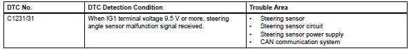
Toyota RAV4 (XA40) 2013-2018 Service Manual: Steering angle sensor circuit malfunction
![]()
Description
The steering sensor signal is sent to the skid control ecu via the can communication system. When there is a malfunction in the can communication system, it is detected by the steering sensor zero point malfunction diagnostic function.
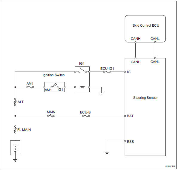
Wiring diagram
Inspection procedure
Hint:
- When u0073/94, u0123/62, u0124/95 or u0126/63 is output together with c1231/31, inspect and repair the trouble areas indicated by u0073/94, u0123/62, u0124/95 or u0126/63 first.
- When there are problems with the speed sensor or the yaw rate sensor, dtcs for the steering sensor may be output even when the steering sensor is normal. When dtcs for the speed sensor or yaw rate sensor are output together with other dtcs for the steering sensor, inspect and repair the speed sensor and yaw rate sensor first, and then inspect and repair the steering sensor.
- Check harness and connector (momentary interruption)
- Using the data list of the intelligent tester, check for any momentary interruptions in the wire harness and connectors between the skid control ecu and the steering sensor (see page bc-23).
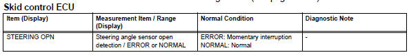
Ok: there are no momentary interruptions.
Hint:
Perform the above inspection before removing the sensor and connector.

- Check dtc
- Clear the dtc (see page bc-47).
- Turn the ignition switch off
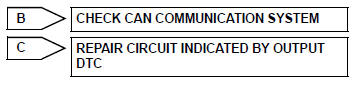
- Turn the ignition switch on again and check that no can communication system dtc is output.
- Drive the vehicle and turn the steering wheel to the right and left at a speed of 35 km/h (24 mph) and check that no speed and yaw rate sensor dtcs are output.
Result 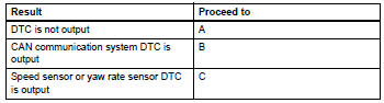

- Check wire harness (steering sensor - battery and body ground)
- Remove the steering wheel assembly and the column cover.
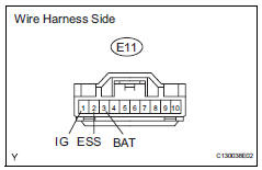
- Disconnect the e11 sensor connector.
- Measure the voltage of the wire harness side connector.
Standard voltage 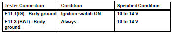
- Measure the resistance of the wire harness side connector.
Standard resistance 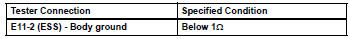

Replace steering sensor
- Repair or replace harness and connector (steering sensor to skid control ecu)

- Reconfirm dtc
- Clear the dtc (see page bc-47).
- Start the engine.
- Drive the vehicle and turn the steering wheel to the right and left at a speed of 45 km/h (28 mph) or more for several seconds.
- Check if the same dtc is recorded (see page bc-47).
Result 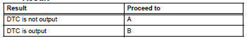

End
 Abs control system malfunction
Description
This dtc is output when the vsc system detects a malfunction in the abs
system.
Inspection procedure
Check dtc for abs system
Clear the dtc (see page bc-47).
Turn t ...
 Stuck in deceleration sensor
Description
The skid control ecu receives signals from the yaw rate and deceleration
sensor via the can
communication system.
The yaw rate sensor has a built-in deceleration sensor and dete ...
Other materials:
Inspection
Inspect starter assembly
Notice:
These tests must be performed within 3 to 5 seconds
to avoid burning out the coil.
Perform the pull-in test.
Disconnect the lead wire from terminal c.
Connect the battery to the magnetic switch as
shown in the illustration. Check that the clutch ...
Back door outside garnish
Components
Removal
Disconnect cable from negative battery
terminal
Caution:
Wait at least 90 seconds after disconnecting the
cable from the negative (-) battery terminal to
prevent airbag and seat belt pretensioner activation.
Remove back door center garnish (see page
ed-5 ...
Dtc check / clear
Check dtc (using sst (check wire))
Check the dtcs (present trouble code).
Turn the ignition switch on, and wait for
approximately 60 seconds.
Using sst, connect terminals 13(tc) and 4(cg)
of the dlc3.
Sst 09843-18040
Notice:
Connect the terminals to the correct
positio ...
