Toyota RAV4 (XA40) 2013-2018 Service Manual: Stop light switch circuit
Description
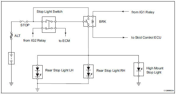
When the stop light switch is turned on, current flows to the stop lights to illuminate them.
Wiring diagram
Inspection procedure
- Inspect fuse (stop)
- Remove the stop fuse from the instrument panel junction block.
- Measure the resistance of the fuse.
Standard resistance:
below 1 


- Inspect stop light (rear combination light)
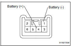
- Remove the rear combination light.
- Connect the positive (+) lead from the battery to terminal 4 and the negative (-) lead to terminal 1, then check that the light comes on.
Ok: light comes on.


- Inspect rear stop light (high mount stop light)
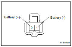
- Remove the high mount stop light assembly.
- Connect the positive (+) lead from the battery to terminal 2 and the negative (-) lead to terminal 1, then check that the light comes on.
Ok: light comes on


- Inspect brk relay
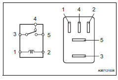
- Remove the brk relay from the engine room no. 1 Relay block.
- Measure the resistance of the relay.
Standard resistance


- Inspect stop light switch
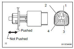
- Remove the stop light switch.
- Measure the resistance of the switch.
Standard resistance


- Check wire harness (stop light switch - battery)
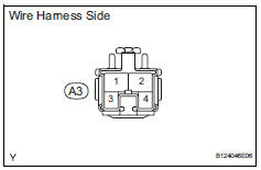
- Disconnect the a3 stop light switch connector.
- Measure the voltage of the wire harness side connector.
Standard voltage 


- Check wire harness (stop light switch - rear stop light)
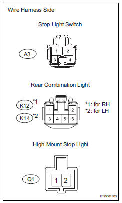
- Disconnect the a3 stop light switch connector.
- Disconnect the k12 and k14 rear combination light connectors.
- Disconnect the q1 high mount stop light connector.
- Measure the resistance of the wire harness side connectors.
Standard resistance 


Repair or replace harness and connector (rear stop light - body ground)
 Data list / active test
Read data list
Hint:
Using the intelligent tester's data list allows switch,
sensor, actuator and other item values to be read without
removing any parts. Reading the data list early in
...
 Headlight relay circuit
Description
When the light control switch, located on the headlight dimmer switch, is
turned to the head position, the
head relay illuminates the headlights.
Wiring diagram
Inspection proced ...
Other materials:
Installation
Caution:
Be sure to read the precautionary notices concerning the
srs airbag system before servicing it (see page rs-1).
Install roof side rail bracket lh
Install the bracket with the 2 bolts.
Torque: 14 n*m (143 kgf*cm, 10 ft.*Lbf)
Install curtain shield airbag assembly lh ...
Occupant classification ecu
Components
On-vehicle inspection
Inspect occupant classification ecu
(vehicle not involved in collision)
Perform a diagnostic system check (see page rs-
236).
Inspect occupant classification ecu
(vehicle involved in collision)
Perform a diagnostic system check (see p ...
Short in front driver side - side squib circuit
Description
The driver side - side squib circuit consists of the center airbag sensor and
the front seat side airbag lh.
This circuit instructs the srs to deploy when the deployment conditions are met.
These dtcs are recorded when a malfunction is detected in the driver side - side
sq ...
