Toyota RAV4 (XA40) 2013-2018 Service Manual: Terminals of ecu
- Skid control ecu
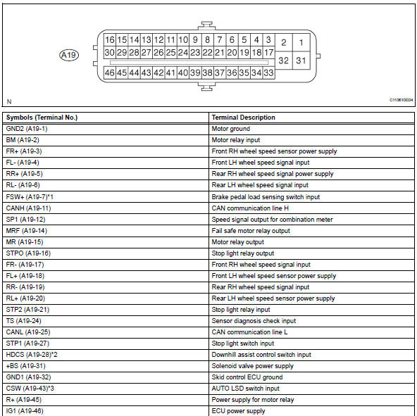
Hint:
*1: W/ 16-inch disc
*2: W/ downhill assist control
*3: For 2wd (w/ auto lsd)
- Check skid control ecu
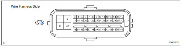
- Disconnect the a19 ecu connector.
- Measure the voltage and resistance of the wire harness side connector.
Hint:
The voltage cannot be measured with the connector connected to the skid control ecu as the connector is water resistant.
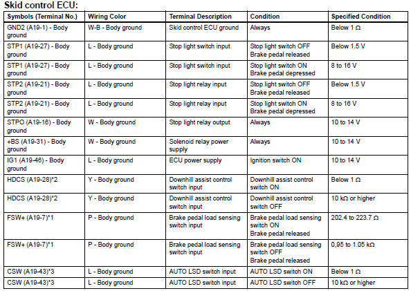
Hint:
*1: W/ 16-inch disc
*2: W/ downhill assist control
*3: For 2wd (w/ auto lsd)
If the result is not as specified, there may be a malfunction on the wire harness side.
- Check instrument panel junction block (main body ecu)
- Disconnect the id junction block connector.
- Measure the resistance of the wire harness side connector.

If the result is not as specified, there may be a malfunction on the wire harness side.
- Reconnect the id junction block connector.
- Measure the voltage of the wire harness side connector.

If the result is not as specified, the junction block (ecu) may be a malfunction.
 Problem symptoms table
Hint:
Use the table below to help determine the cause of the
problem symptom. The potential causes of the symptoms
are listed in order of probability in the "suspected area"
column ...
 Diagnosis system
Diagnosis
If the skid control ecu detects a malfunction, the abs,
vsc and brake warning lights and the slip, downhill
assist control and auto lsd indicator lights come on in
accordance with t ...
Other materials:
Evaporative emission control system pressure sensor
Dtc summary
Hint:
The canister pressure sensor is built into the canister pump module.
Description
The description can be found in the evap (evaporative emission) system (see
page es-335).
Monitor description
Dtc p0450: canister pressure sensor abnormal fluctuation
If t ...
Circuit opening relay
On-vehicle inspection
Disconnect cable from negative battery
terminal
Caution:
Wait at least 90 seconds after disconnecting the
cable from the negative (-) battery terminal to
prevent airbag and seat belt pretensioner activation.
Inspect instrument panel junction block
Notice:
Th ...
Front door courtesy switch
Components
Removal
Hint:
Use the same procedures for the rh and lh sides.
The procedures listed below are for the lh side.
Disconnect cable from negative battery
terminal
Caution:
Wait at least 90 seconds after disconnecting the
cable from the negative (-) battery terminal t ...
