Toyota RAV4 (XA40) 2013-2018 Service Manual: Terminals of ecu (2005/11-2006/01)
- Check air conditioning amplifier
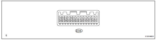
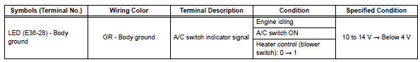
- Measure the voltage and resistance of the connectors.
Hint:
Check from the rear of the connector while it is connected to the air conditioning amplifier.
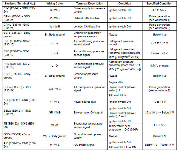
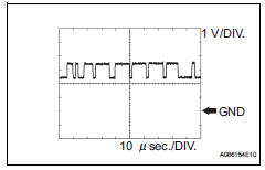
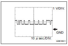
- using an oscilloscope, check waveform 1.
Can communication signal 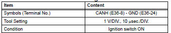
Hint:
The waveform varies depending on the can communication signal.
- Using an oscilloscope, check waveform 2.
Can communication signal 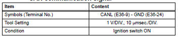
Hint:
The waveform varies depending on the can communication signal.
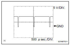
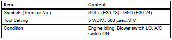
- Using an oscilloscope, check waveform 3.
Compressor and pulley operation signal
 Problem symptoms table (2006/01- )
Hint:
Use the table below to help determine the cause of the
problem symptom. The potential causes of the symptoms
are listed in order of probability in the "suspected area"
colum ...
 Terminals of ecu (2006/01- )
Check air conditioning amplifier
Measure the voltage and resistance of the
connectors.
Hint:
Check from the rear of the connector while it is
connected to the air conditioning ampl ...
Other materials:
Selecting the driving mode
The following modes can be selected to suit driving conditions.
Eco drive mode
Use eco drive mode to help achieve low fuel consumption during
trips that involve frequent accelerating.
Press the “eco mode” button
to select eco drive mode.
The “eco mode” indicator
comes on.
Press t ...
Fuel consumption information
The fuel consumption information
can be displayed on
the Multimedia Display.
Display procedure
Press on the main menu,
then press "Trip information" on
the sub menu.
For detail regarding the Multimedia
Display, refer to "MULTIMEDIA
OWNER'S MANUAL".
â– Current fuel consumption
screen
If a screen o ...
Cooling fan relay
On-vehicle inspection
Disconnect cable from negative battery
terminal
Caution:
Wait at least 90 seconds after disconnecting the
cable from the negative (-) battery terminal to
prevent airbag and seat belt pretensioner activation.
Remove engine room no. 2 Relay block
cover
Inspect ...
