Toyota RAV4 (XA40) 2013-2018 Service Manual: Valve body
Components
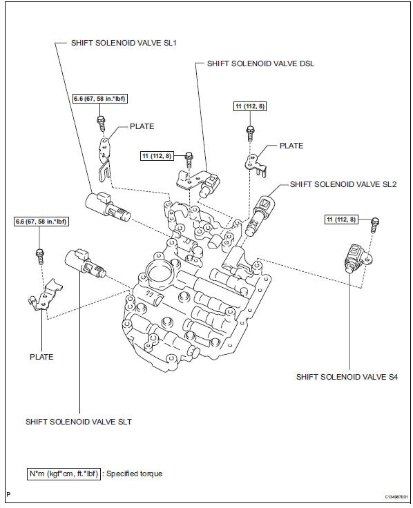
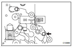
Disassembly
- Remove shift solenoid valve slt
- Remove the bolt, plate and shift solenoid valve slt from the valve body.
- Remove shift solenoid valve sl1
- Remove the bolt, plate and shift solenoid valve sl1 from the valve body.
- Remove shift solenoid valve dsl
- Remove the bolt and shift solenoid valve dsl from the valve body.
- Remove shift solenoid valve sl2
- Remove the bolt, plate and shift solenoid valve sl2 from the valve body.
- Remove shift solenoid valve s4
- Remove the bolt and shift solenoid valve s4 from the valve body.
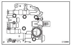
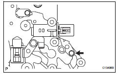
- Remove manual valve
- Remove the manual valve from the valve body.
Reassembly
- Install manual valve
- Install the manual valve to the valve body.
- Install shift solenoid valve s4
- Install the shift solenoid valve s4 to the valve body with the bolt.
Torque: 11 n*m (112 kgf*cm, 9 ft.*Lbf)
- Install shift solenoid valve sl2
- Install the shift solenoid valve sl2 to the valve body with the bolt and plate.
Torque: 11 n*m (112 kgf*cm, 8 ft.*Lbf)
- Install shift solenoid valve dsl
- Install the shift solenoid valve dsl to the valve body with the bolt.
Torque: 11 n*m (112 kgf*cm, 8 ft.*Lbf)
- Install shift solenoid valve sl1
- Install the shift solenoid valve sl1 to the valve body with the bolt and plate.
Torque: 6.6 N*m (67 kgf*cm, 58 in.*Lbf)
- Install shift solenoid valve slt
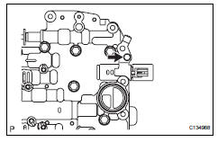
- Install the shift solenoid valve slt to the valve body with the bolt and plate.
Torque: 6.6 N*m (67 kgf*cm, 58 in.*Lbf)
 Underdrive clutch
Components
Disassembly
Inspect pack clearance of underdrive
clutch (see page ax-247)
Remove no. 1 Underdrive clutch disc
Using a screwdriver, pry out the underdrive clutch
fla ...
 Differential case
Components
Disassembly
Remove front differential ring gear
Place the matchmarks on the ring gear and
differential case.
Remove the 14 bolts.
Using a plastic-fa ...
Other materials:
Check and replace ecu
Notice:
The connector should not be disconnected from
the ecu. Perform the inspection from the
backside of the connector on the wire harness
side.
When no measuring condition is specified,
perform the inspection with the engine stopped
and the ignition switch on.
Check that the con ...
Components
...
Using the steering
wheel switches
The steering wheel switches can be used to operate a connected
cellular phone.
Operating a telephone using the steering wheel switches
Volume switch
Increase/decrease the volume
Press and hold:
continuously increase/
decrease the volume
Enter switch
Select an item
...
