Toyota RAV4 (XA40) 2013-2018 Service Manual: Blower motor circuit
Description
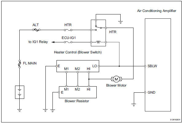
When the heater control (blower switch) is set to position 1 or higher, the contact of the htr relay is closed, current flows to the blower motor, and the blower motor operates. The blower motor speed can be changed by exchanging the ground and the blower resistor circuit with the heater control (blower switch).
Wiring diagram
Inspection procedure
- Inspect fuse (htr)
- Remove the htr fuse from the engine room no. 2 Relay block.
- Measure the resistance of the fuse.
Standard resistance:
below 1

- Inspect heater relay (marking: htr)
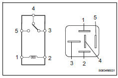
- Remove the heater relay from the instrument panel junction block.
- Measure the resistance of the relay.
Standard resistance 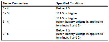

- Inspect blower motor
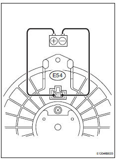
- Disconnect the e54 motor connector.
- Connect the positive (+) lead from the battery to terminal 2 and the negative (-) lead to terminal 1, then check that the blower motor operates smoothly.
Ok: the blower motor operates smoothly.
- Measure the current.
Standard current 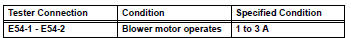

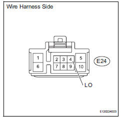
- Check wire harness (heater control (blower switch) - battery)
- Disconnect the e24 heater control connector.
- Measure the voltage of the wire harness side connector.
Standard voltage 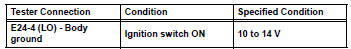

- Inspect heater control (blower switch)
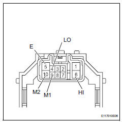
- Remove the heater control.
- Measure the resistance of the switch.
Standard resistance 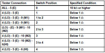

- Inspect blower resistor
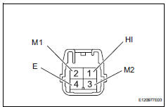
- Remove the blower resistor.
- Measure the resistance of the resistor.
Standard resistance 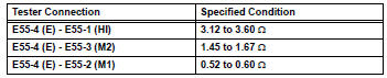

- Check wire harness (heater control (blower switch) - blower resistor)
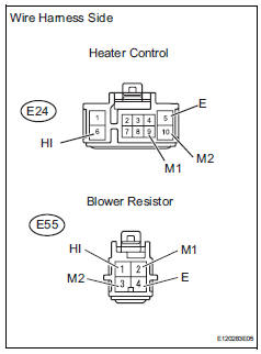
- Disconnect the e24 heater control connector.
- Disconnect the e55 blower resistor connector.
- Measure the resistance of the wire harness side connectors.
Standard resistance 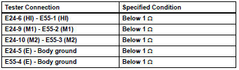

- Check wire harness (blower resistor - blower motor)
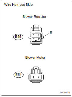
- Disconnect the e55 blower resistor connector.
- Disconnect the e54 motor connector
- Measure the resistance of the wire harness side connectors.
Standard resistance 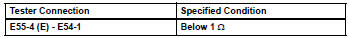

- Check wire harness (blower motor - body ground)
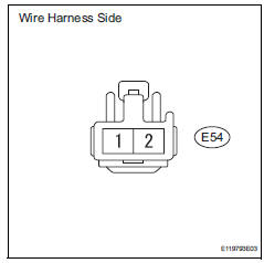
- Disconnect the e54 motor connector.
- Measure the resistance of the wire harness side connector.
Standard resistance 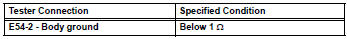
- Measure the voltage of the wire harness side connector.
Standard voltage 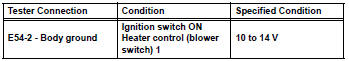

- Check wire harness (air conditioning amplifier - battery)
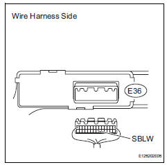
- Disconnect the e36 amplifier connector.
- Measure the voltage of the wire harness side connector.
Standard voltage 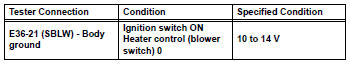

- Check wire harness (air conditioning amplifier - body ground)
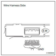
- Disconnect the e36 amplifier connector.
- Measure the resistance of the wire harness side connector.
Standard resistance 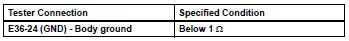

Proceed to next circuit inspection shown in problem symptoms table
 Multiplex communication circuit
Description
The air conditioning amplifier communicates data with the ecm and combination
meter through the can
communication system.
Wiring diagram
Inspection procedure
Check dt ...
 Compressor circuit
Description
When the a/c switch is turned on, the magnetic clutch on signal is sent from
the air conditioning
amplifier. Then the mg clt relay turns on to operate the magnetic clutch.
Wiring diag ...
Other materials:
Installation
Install drive plate sub-assembly
Clean the 8 bolts and 8 bolt holes.
Apply adhesive to 2 or 3 threads of the 8 bolts.
Adhesive:
Toyota genuine adhesive 1342, three bond
1342 or equivalent
Using sst, hold the crankshaft.
Sst 09213-54015 (91651-60855), 09330-00021
Instal ...
Disassembly
Remove idler pulley (see page em-23)
Remove oil dipstick
Remove oil dipstick guide (see page em-57)
Remove manifold stay (see page em-57)
Remove no. 2 Manifold stay (see page em-58)
Remove no. 1 Exhaust manifold heat
insulator (see page em-58)
Remove exhaust manifold converter subas ...
Inspection
Inspect crankshaft position sensor
Measure the resistance of the sensor.
Standard resistance
Notice:
Cold and hot mean the temperature of the coils
themselves. Cold is from -10 to 50°c (14 to
122°f) and hot is from 50 to 100°c (122 to
212°f).
If the result is not as specif ...
