Toyota RAV4 (XA40) 2013-2018 Service Manual: Compressor circuit
Description
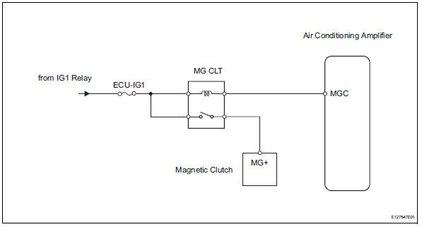
When the a/c switch is turned on, the magnetic clutch on signal is sent from the air conditioning amplifier. Then the mg clt relay turns on to operate the magnetic clutch.
Wiring diagram
Inspection procedure
Inspection procedure
- Perform active test by intelligent tester (a/c mag clutch)
- Connect the intelligent tester (with can vim) to the dlc3.
- Turn the ignition switch on and turn the intelligent tester main switch on.
- Select the item below in the active test and then check that the compressor magnetic relay operates.


- Inspect fuse (ecu-ig1)
- Remove the ecu-ig1 fuse from the instrument panel junction block.
- Measure the resistance of the fuse.
Standard resistance:
below 1


- Inspect magnetic clutch relay (marking: mg clt)
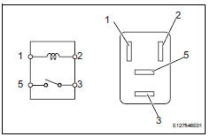
- Remove the magnetic clutch relay from the engine room no. 1 Relay block.
- Measure the resistance of the relay.
Standard resistance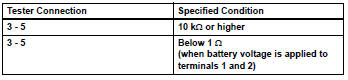


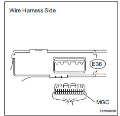
- Check wire harness (air conditioning amplifier - battery)
- Disconnect the e36 amplifier connector.
- Measure the voltage of the wire harness side connector.
Standard voltage 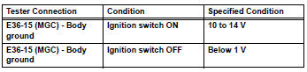

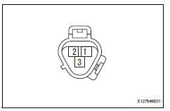
- Check air conditioning amplifier (mgc voltage)
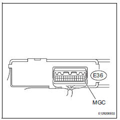
- Remove the air conditioning amplifier with its connectors still connected.
- Measure the voltage of the connector.
Standard voltage 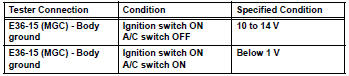


- Check magnetic clutch
- Disconnect the b47 magnetic clutch connector.
- Connect the battery's positive (+) lead to terminal 3 of the magnetic clutch and the negative (-) lead to the body ground.
Ok: magnetic clutch is engaged.


Repair or replace wire harness (magnetic clutch - ecu-ig1)
 Blower motor circuit
Description
When the heater control (blower switch) is set to position 1 or higher, the
contact of the htr relay is
closed, current flows to the blower motor, and the blower motor operates. The
...
 Ig power source circuit
Description
This is the main power source supplied to the air conditioning amplifier when
the ignition switch is on.
This power source is used for operating components, such as the air condition ...
Other materials:
Open in one side of can branch line
Description
If 2 or more ecus and/or sensors do not appear on the intelligent tester's
"bus check" screen via the
can vim, one side of the can branch wire may be open. (One side of the canh
[branch wire] /canl
[branch wire] of the ecu and/or sensor is open.)
Wiring diagram
...
Parts location
System diagram
System description
Cruise control system
This system is controlled by the ecm, and is activated by
the throttle position sensor and motor. The ecm controls
the following functions: on-off, set / coast,
resume / accel, cancel, vehicle speed operation,
motor ...
Customer problem analysis
Hint:
In troubleshooting, confirm that the problem symptoms
have been accurately identified. Preconceptions should be
discarded in order to make an accurate judgment. To
clearly understand what the problem symptoms are, it is
extremely important to ask the customer about the
problem an ...
