Toyota RAV4 (XA40) 2013-2018 Service Manual: How to proceed with troubleshooting
Hint:
- Use these procedures to troubleshoot the seat belt warning system.
- *: Use the intelligent tester.
- Vehicle brought to workshop

- Inspect battery voltage
Standard voltage: 11 to 14 v
If the voltage is below 11 v, recharge or replace the battery before proceeding.

- Check function of airbag system*
- Use the intelligent tester to check if the airbag system is functioning normally.
Result 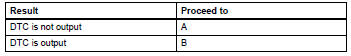

- Check function of occupant classification system*
- Use the intelligent tester to check if the occupant classification system is functioning normally.
Result 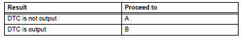

- Check communication function of can communication system (can)*
- Use the intelligent tester to check if the can communication system (can) is functioning normally.
Result 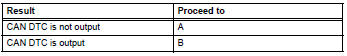

- Problem symptoms table
Result 


- Overall analysis and troubleshooting*
- Data list / active test (see page sb-10)
- Terminals of ecu (see page sb-7)
- On-vehicle inspection (see page sb-10)

- Repair or replace

- Confirmation test

End
 System description
Driver seat belt warning light
When the driver seat belt is not fastened with the
ignition switch on, the driver seat belt warning light
on the combination meter comes on to inform the
...
 Operation check
Inspect driver side seat belt warning light
Turn the ignition switch on.
When the driver seat belt is not fastened, check that
the driver seat belt warning light on the combination
mete ...
Other materials:
Precaution
If any of following conditions are met,
keep engine idling with a/c on (engine
speed at less than 2000 rpm) for at least 1
minute:
Refrigerant gas has been refilled or a/c parts have
been replaced.
A long time has elapsed since the engine was
stopped.
Notice:
If the engine s ...
Contact/call history
settings
The contact can be transferred from a bluetooth® phone to the system.
The contact also can be added, edited and deleted.
The call history can be deleted and contact and favorites can be
changed.
Display the “phone/message settings” screen.
Select “contact/call history settings” ...
Parking brake assembly
Components
Disassembly
Hint:
Use the same procedures for the lh side and rh side.
The procedures listed below are for the lh side.
Remove rear wheel
Disconnect rear disc brake cylinder
mounting lh (see page br-55)
Remove parking brake shoe adjusting
hole plug
Remove t ...
